


(Supersedes PK435-4)
PK435-5
WR
161-048630-001
JUNE, 1994
4
Installation
and
OPERATION INSTRUCTIONS
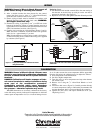
Type WR-80EP Explosion Proof Room Thermostat
© 2010 Chromalox, Inc.
Specifications – Table A
GENERAL
Positive accuracy, long and reliable service, 3° differential. Heavy-
duty, single stage, SPST line voltage snap-acting switch. Patented
hydraulic element. WR-80EP has external, coiled sensing element and
a low position which drops control point to keep heater off.
Uses — Automatically controls room temperature by turning electric
air heaters on and off. Can be used to control the air heaters directly,
within thermostat rating. For higher ratings use thermostat with mag-
netic contactor. Place thermostat on inside wall, away from undue
heating or cooling influences, about 4 feet above the floor. The explo-
sion proof WR-80EP is suitable for Class I, Group D and Class II,
Groups E, F and G locations.
NOTICE: Type WR thermostats are designed for temperature control
service only. Because they do not fail safe, they should not be used for
temperature limiting duty.
WARNING: Users should install adequate back-up con-
trols and safety devices with their electric heating
equipment. Where the consequences of failure may
be severe, back-up controls are essential. Although
the safety of the installation is the responsibility of
the user, Chromalox will be glad to assist in making
equipment recommendations.
Principle of Operation — Control action of these thermostats is pro-
vided through the principle of liquid volume change. With a variation in
temperature, the liquid in the sensing element expands or contracts,
causing a bellows to actuate the switching mechanism.
Housing — The control housing and cover assembly is of heavy-duty
cast aluminum.
Temp. Maximum Rating
Range
Model (°F) 120V a-c † 115V d-c 240V a-c † 230V d-c 277V a-c 480V a-c
125Va pilot 125Va pilot 125Va pilot
WR-80EP 40-90
25 amps duty (use 22 amps duty (use 18 amps duty (use
or 3000 with d-c or 5280 with d-c or 5000 with a-c
total watts contactor) total watts contactor) total watts contactor)
† d-c ratings not UL listed
4”
6
1
/8”
2
1
/2”
3
11
/16”
WR-80EP
40 to 90°F
UL Listed
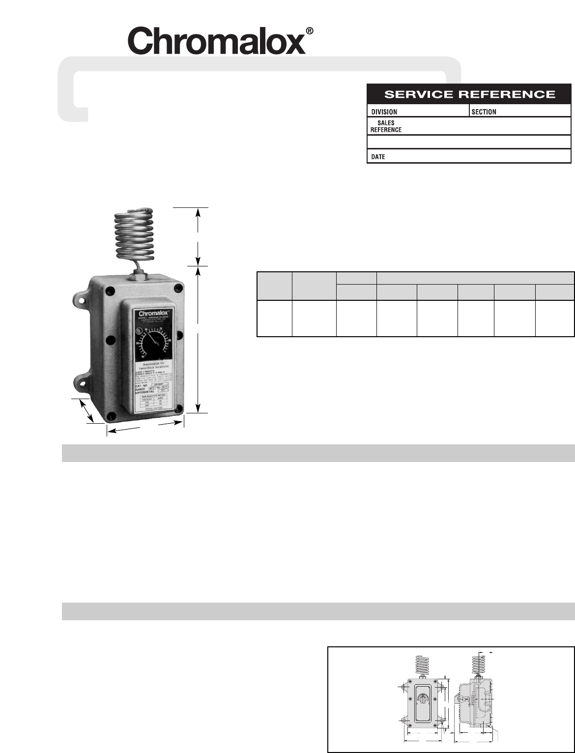
MOUNTING
Note: Do not mount control where it will be subject to vibration,
shock, grease, dust, lint or corrosive vapors. Do not mount adjacent to
a large magnetic contactor, as vibration and shock will cause thermo-
stat to interact erratically – resulting in chattering of the contactor.
WARNING: Do not twist or uncoil the coiled element
on top of the case.
The proper location of a heavy duty room thermostat is important to
assure good performance.
1. Locate where air circulates freely.
2. Never install on or near outside wall.
3. Keep away from windows or doors.
4. Do not locate too close to strong light or other false source of heat,
such as sunlight, steam lines, etc.
5. If electrical conduit leads into cooler or warmer room, plug up
space around wires in the conduit with rock wool.
1 /
1
16
1 /
1
16
11
16
1 /
11
16
3 /
5
8
4 /
5
8
4 /
4
1
6 /
8
15
16
2 /
1
2
/ -14
N.P.T. Thread
4-Holes
/ " Dim.
5
16
5
8
/
Figure 1