


WIRING
Note: All wiring should be done in accordance with local codes
and the National Electrical Code by a qualified person.
WARNING: Hazard of Electric Shock. Any installation
involving electric heaters must be effectively
grounded in accordance with the National Electrical
Code to eliminate shock hazard.
1. Connect heater according to the voltage and frequency speci-
fied on the nameplate and using the appropriate wiring diagram
(Figures 3 thru 8).
Note: Be sure to check voltage rating of the fan motor which is
either 120, 208 or 240 volt, single phase since heater circuit
could be 480 volts, single or three phase.
2. If a transformer is used to step down the voltage for operating
the fan motor, use appropriate wiring diagram (Figures 5 or 7).
3. Heaters are not provided with a control switch and should be
controlled by a magnetic contactor (integral or external) and a
separately mounted thermostat. External contactor is not nec-
essary with heaters having a model number suffixed with the
letter “R”.
4. Protection against overheating is provided by an internal auto-
matic thermal cutout which opens the electric circuit if the nor-
mal air-flow is restricted or stopped. Cutout automatically
energizes heater on removal of the obstruction.
WARNING: Users should install adequate back-up
controls and safety devices with their electric heat-
ing equipment. Where the consequences of failure
may be severe, back-up controls are essential.
Although the safety of installation is the responsi-
bility of the user, Chromalox will be glad to make
equipment recommendations.
OPERATION
DANGER:
1. Do not restrict air-flow through the heater by
placing fabric or other obstructions in front of or
behind the heaters. With some combustible
materials, the resulting high discharge tempera-
tures could cause a fire.
2. This heater is not intended for use in hazardous
atmospheres where flammable vapors, gases, liq-
uids or other combustible atmospheres are present
as defined in the National Electrical Code. Failure
to comply can result in explosion or fire. For these
applications see Bulletin PDS CXH-EP PF305.
MAINTENANCE
WARNING: Turn off all power to service heater. Do not
attempt to service heater while unit is operating as
there is hazard of electric shock, injury from operat-
ing fan, and burns from hot heating elements.
1. Fan motors in these heaters are provided with sealed ball bear-
ings, factory lubricated, requiring no further lubrication under
normal service conditions.
2. Following long periods of idleness, heater should be vacu-
umed before start-up, to remove accumulated combustible par-
ticles which otherwise may smoke or incinerate on initial heat
up.
3. Periodically inspect all electrical connections and terminals to
avoid electrical wiring difficulties. Inspect all wiring for frayed
or worn insulation.
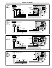
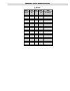
WIRING DIAGRAMS
Ground
Heater Bank
1Ø Motor
Heater
Wiring Comp't
Baffle
For 3 Phase Only
This Wiring
by Customer
Thermostat When Used
Control Source for
Separately Wired Motors
120 or 240 Volts, 60 Cycle
1 or 3 Phase 60 Hz
Power Supply 120, 208
or 240 Volts
}
Fused
Switch
F1
F2
L1
L2
L3
Fused
Switch
Contactor
When Heater and
Motor Voltage are similar
Figure 3
Use with:
UB-502D
120V, 1Ø
208V, 1Ø or 3Ø
240V, 1Ø or 3Ø
UB-752D
208V, 3Ø
240V, 3Ø
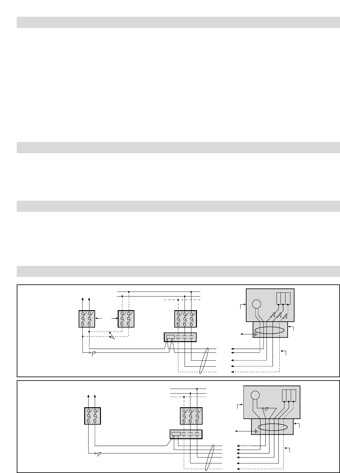
Ground
Heater Bank
1Ø Motor
Heater
Wiring Comp't
Baffle
For 3 Phase Only
This Wiring
by Customer
Thermostat When Used
Control Source for
Separately Wired Motors
120 or 240 Volts, 60 Cycle
1 or 3 Phase 60 Hz
Power Supply 208, 240
or 480 Volts
Cutout
}
Fused
Switch
F1
F2
T1
L1
L2
L3
Fused
Control Switch
Contactor
Figure 4
Use with:
UB-502D &
UB-752D
480V, 1Ø or 3Ø
UB-752D
208V, 1Ø
208V, 1Ø