


3
3
9
2
Scribe
Line on
Extrusion
5
6
1
5
6
2
8
10
2x Loop of Grill
4
7
2x Prong of Grill
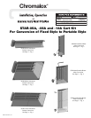
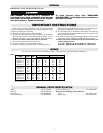
6.0 kW UNIT CONVERSION INSTRUCTIONS
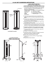
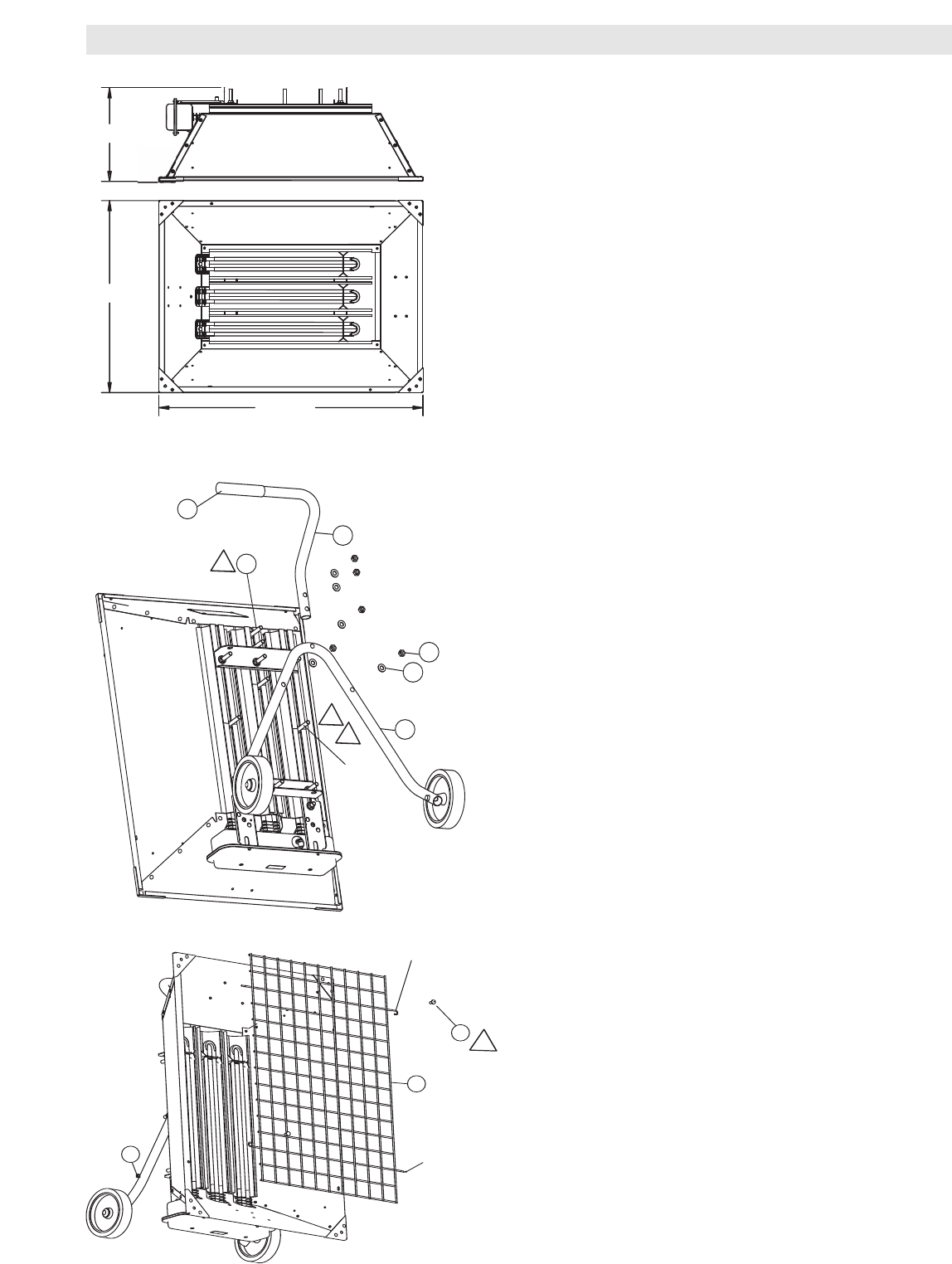
23-5/8"
32-1
/
2
"
11-1/2"
6.0kW Fixed Style Heater
INSTRUCTIONS FOR CONVERTING
A FIXED STYLE INTO A PORTABLE STYLE
(Installation of Cart making it a Portable Heater Voids UL Listing)
1. The kit (168-053169-079) that converts a 6.0 KW fixed style radiant
heater includes the following parts. Verify that all parts are included, if
not, contact the Chromalox Service Department at 1-800-368-2493.
(1) Lower Leg (10) 1/4-20 x 1/2” Long Bolt (4 Req’d)
(2) Axle (11) 1/4-20 Square nut (4 Req’d)
(3) Wheel (2 Req’d) (12) Pop Rivet (4 Req’d)
(4) Cap (2 Req’d) (13) No. 10 Sheet Metal Screw ( Req’d)
(5) Upper Handle (14) 3/8-16 x 1-1/2” Long Bolts (2 Req’d)
(6) Front Leg (15) 3/8-16 Nuts (2 Req’d)
(7) Grip (16) 3/8 Lockwashers (2 Req’d)
(8) Grille (17) 10-32 x 1/2” Long Self Tapping
(9) Baffle Screw (2 Req’d)
2. Using hammer tap cap (4) onto one end of axle (2). Slide one wheel
(3) onto axle. Slide end of axle through both holes of lower leg (1).
Slide remaining wheel onto portion of axle protruding through lower
leg. Tap cap on axle.
3. Remove Lower Bracket by removing nuts and washers.
4. Slide the two (2) 3/8” bolts in the outer extrusions to the 4-1/2”
dimension and the one (1) 3/8” bolt in the center extrusion to the 8-
15/16” dimension.
5. Place lower leg assy made in step 2 onto the three (3) bolts. Secure in
place with washers and nuts removed in step 3.
6. Loosen three nuts on upper bracket and reposition to the 3” dimension
shown.
7. Slide the two 3/8-16 x 1-1/2” long bolts (14) into the top center extru-
sion. Locate one at 3/4” and the other at 2-1/4” as shown.
8. Place upper handle (5) onto two bolts. Secure in place with washers
and nuts provided.
9. Slide grip (7) onto end of upper handle (5).
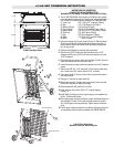
10.Stand heater vertically. If heater does not sit evenly, loosen nuts that
secure lower leg assy and adjust accordingly.
11.Rotate heater back until handle (5) is on floor.
12.Install front leg (6) with two 10-32 x 1/2” long self tapping
screws (17).
13.Install baffle (8) using pop rivets, if pop rivet gun is not available use
the No. 10 sheet metal screws.
14.Place grille prongs into slots of reflector using a counterclockwise rota-
tion see Detail A. Insert 1/4-20 screws through looped end of grille
with 1/4-20 square nut on opposite side. Tighten screws with screw
driver.
15.If fixed heater is being converted to a portable by the factory, then drill
out nameplate rivets and replace nameplate with 196-891789-004.
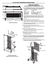
6.0 kW Fixed Style Heater
Modified to add cart, baffle and grille