


ELECTRIC SHOCK HAZARD. Disconnect all power
before installing or servicing heater. Failure to do so
could result in personal injury or property damage.
Heater must be installed by a qualified person in accor-
dance with the National Electrical Code, NFPA 70.
ELECTRIC SHOCK HAZARD. Any installation involv-
ing electric heaters must be performed by a quali-
fied person and must be effectively grounded in
accordance with the National Electrical Code to
eliminate shock hazard.
1. Electric connection to the Radiant Heater is made through two
openings tapped for 1/2” connector. Openings are in the top of
the extruded heater housing, one near each end.
2. Access to Radiant Heater terminals is obtained by removing
the two screws in each of the terminal box covers.
3. Wiring should run in flexible or rigid metal conduit and must
be installed in accordance with the requirements of the
National Electrical Code and such other local requirements by
a qualified person.
4. Wires supplying power to heating element terminals shall have
insulation rated for 150˚C Minimum.
High temperatures will oxidize copper. Use only
nickel-plated copper wire for supplying power to
heater. Do not use aluminum conductors.
5. A sufficient length of this wire (not less than 12”) should be
used to extend from each heater terminal into a connection box
location where the temperature does not exceed 300˚F.
6. Leave generous loop in wire when connecting to allow for
expansion of heating element.
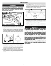
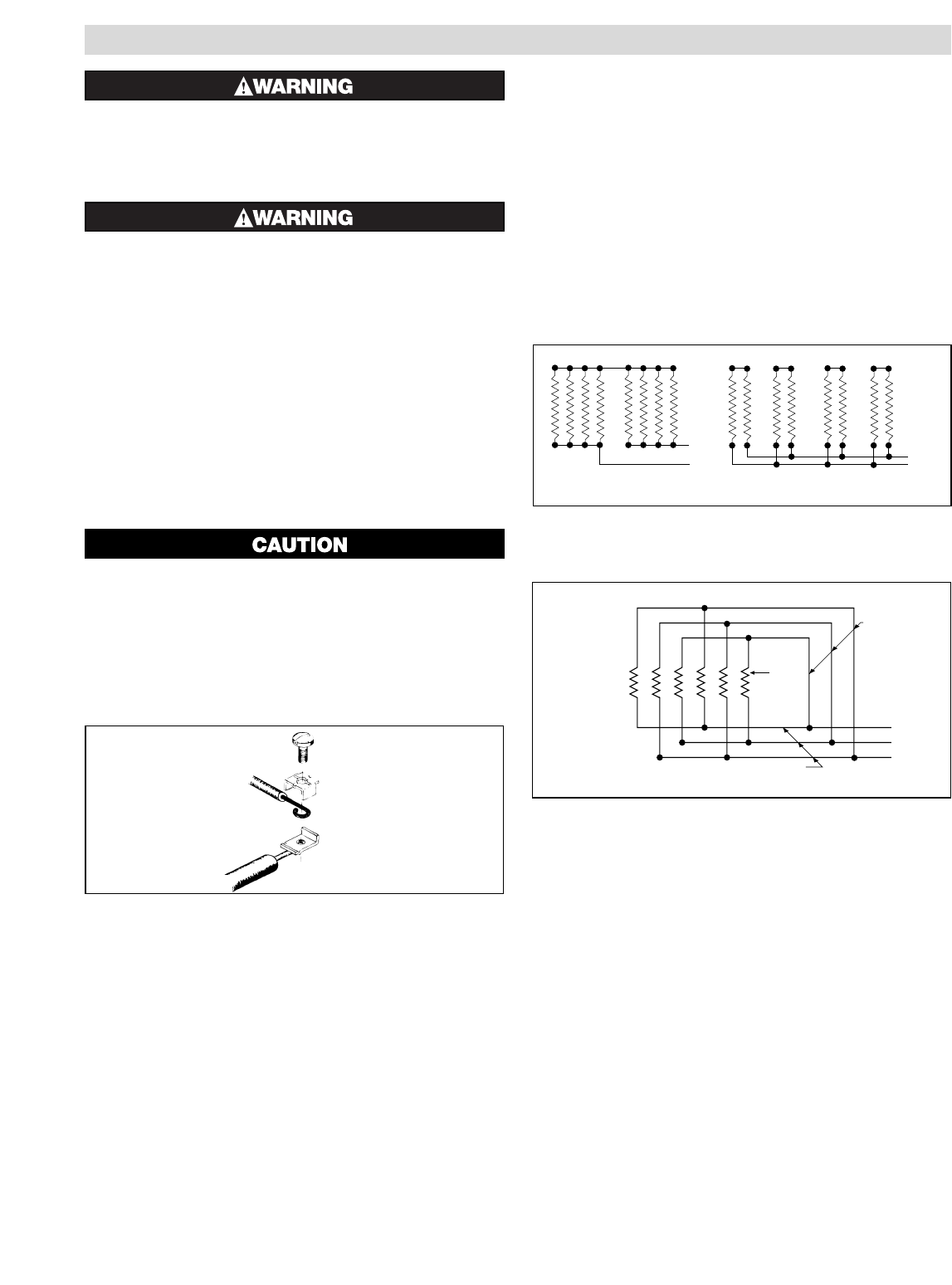
7. Assemble terminal, screw and wire as shown in Figure 5.
8. Hold terminal with pliers and tighten the terminal screw
securely with a screwdriver.
Note: Where circuit wiring is installed in locations of high
ambient temperature, conductors should be insulated in accor-
dance with requirements for temperature and voltage.
9. SINGLE END WIRING may be made through one of the
wiring entries by bringing a lead through it from the opposite
end of the heating element using the wire-way provided behind
integral reflector in the housing extrusion. Wire used in mak-
ing such connections must be able to operate in high ambient
and have a sufficiently high voltage rating for the specific
application. The maximum wire diameter is limited by the
wire-way and must not exceed .224” over the insulation.
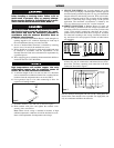
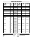
10. SERIES CONNECTION of Radiant Heaters of equal volt
and watt rating is permitted in all line voltages up to 600 volts.
In making such series connections it is necessary to observe the
“right” (series-parallel) connection rather than the “wrong”
(parallel-series) connection both shown in Figure 6. If heaters
are connected according to the “wrong” illustration, failure of
any one heater will cause progressive failure of other heaters
still operating.
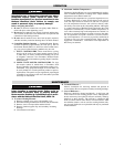
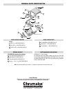
11. DELTA CONNECTIONS – When heaters occur in multiples
of three, they may be connected to, and balanced across, three-
phase lines. The most commonly used connection is the delta
connection illustrated in Figure 7.
Three phase Delta connections to minimize inductive effect in con-
duits are made per this diagram. The rule: run all 3 three-phase con-
ductors in the same conduit as far as possible. For single-phase, run
only two conductors and follow the same rule.
WIRING
L1
L2
L1
L2
Wrong
Right
Radiant
Heaters
Figure 6
L1
L2
L3
Radiant
Heaters
3 Conductors
in 1 Conduit
3 Conductors
in 1 Conduit
FEDCBA
Figure 7
3
Figure 5