


CAUTION: Hazard of Electric Shock. The vaporizer
must be grounded using the grounding means pro-
vided in the heater terminal box and in the control
box, and employ wiring in accordance with the
National Electrical Code.
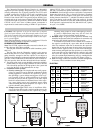
1. The vaporizer is normally supplied one of three different ways:
A. Without controls as they are going to be provided by the
customer. The customer will have to wire from his supplied
controls to the level or float switch on the vessel, and to the
heater terminal blocks and the ground lug in the heater ter-
minal enclosure.
B. With controls supplied, but mounted remotely by the user.
The customer will have to wire from remote controls to the
level or float switch on the vessel, and to the heater terminal
blocks and the ground lug in the heater terminal enclosure.
C. With all controls mounted on the same skid with the
hydraulic or mechanical part of the vaporizer. The unit is
completely wired. The only wiring necessary is to terminals
L1, L2 and L3 on the main circuit breaker and the ground-
ing lug in the control panel.
2. Note: All electrical connections should be checked and tight-
ened if necessary. These sometimes loosen in transit.
CAUTION: Hazard of Electric Shock. Disconnect all
power before servicing the vaporizer.
INSTALLATION
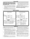
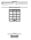
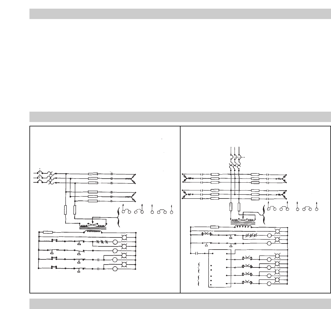
WIRING DIAGRAMS
OPERATION
CAUTION: To avoid possible damage to the heaters, do not ener-
gize the heaters until the vaporizer is filled with fluid.
1. The filling of the Chromalox CHTV type horizontal vaporizer
is accomplished in one of two ways:
A. On vaporizers with gravity return type condensate return
systems, the filling is done simply by pouring the heat
transfer or other organic media into the vaporizer shell
using the spare or fill nozzle and, while the filling is taking
place, bleeding the displaced air from the vent.
B. On vaporizers that use pump condensate return systems or
on systems where the condensate is not returned, the filling
would be done by first filling the condensate return tank or
supply or reservoir tank and then energizing the condensate
return or supply pump. While the vaporizer vessel is being
filled, the vent nozzle should be opening for bleeding out
the air.
2. Set the thermostat at 220°F and/or the controlling pressure
switch at its equivalent.
3. To energize the heaters, turn the “on-off” selector switch to the
“on” position. The heaters are interlocked with the level or
float switch located on the vessel, so that the heating element
will shut off automatically in case of a low liquid level.
4. Operate the vaporizer until 220°F is reached. Periodically open
the bleed valves to remove air from the system. At 220°F any
moisture that has been trapped in the system will flash into
steam and can be bled off through the bleeder valves.
WARNING: Avoid having the heat transfer fluid or the fluid to be
vaporized spilled or leaked into the pipeline or vessel insulation as
it has been found that spontaneous ignition of some of these fluids
may result at elevated temperatures.
5. After the vaporizer has been completely charged and free of
steam pockets, set the controlling pressure switch or thermostat to
the pressure or temperature point where the fluid will vaporize.
6. Operate the vaporizer until this set point is reached.
Periodically open the bleeder valves to remove air from the
system.
7. After the system is completely free of air, set the controlling
pressure switch or thermostat to the desired operating point.
Circuit
Breaker
Circuit
Breaker
L1
L2
L3
C1
C2
F1
F2
F3
F4
F5
F6
H4 H2 H3 H1 H4 H2 H3 H1
F8F7
H4
H2 H3
H1
X1 120-Volt X2
240V 480V
Transformer Primary
Pilot Light
Feed or Condensate
Return Pump (Optional)
Pilot Light
High Limit Circuit
Pilot Light
Heat #1
Pilot Light
Heat #2
Off On
Off On
Off On
3
5
7
10
4
6
8
11
9
12
M
CR
C1
C2
1CR
1CR
R
G
A
A
F9
OPC
FS2
FS-1
PSI-1
PSI-2
H4 H2 H3 H1 H4 H2 H3 H1
240V 480V
Transformer Primary
Off On
C1
C2
C3
C4
L1
L2
L3
F1
F2
F3
F4
F5
F6
F7
F8
F9
F10
F11
F12
F13
F14
H4
H3
H2
H1
F15
34
5
6
X1
X2
FS2
FS1
OPC
4-20MA
Input
135 ohm
Input
Stepper
X1
X2
A+
B-
C
D
E
1
2
3
4
1CR
1CR
Off On
Off On
Off On
Off On
7
8
9
10
11
12
13
14
15
M
R
G
A
C1
C2
C3
C4
A
A
A
Pilot LIght
Feed or Condensate
Return Pump (Optional)
Pilot Light
Low Level and
High Limit Circuit
Pilot Light
Heat #1
Pilot LIght
Heat #2
Pilot LIght
Heat #3
Pilot LIght
Heat #4
Typical Wiring Diagram
15 to 100 kW (All Voltages)
Typical Wiring Diagram
125 to 300 kW 440/480 and 550/575V