


WIRING (cont’d.)
Wiring Entrance Locations - Moisure Resistant Housing Only
(E4 Option)
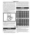
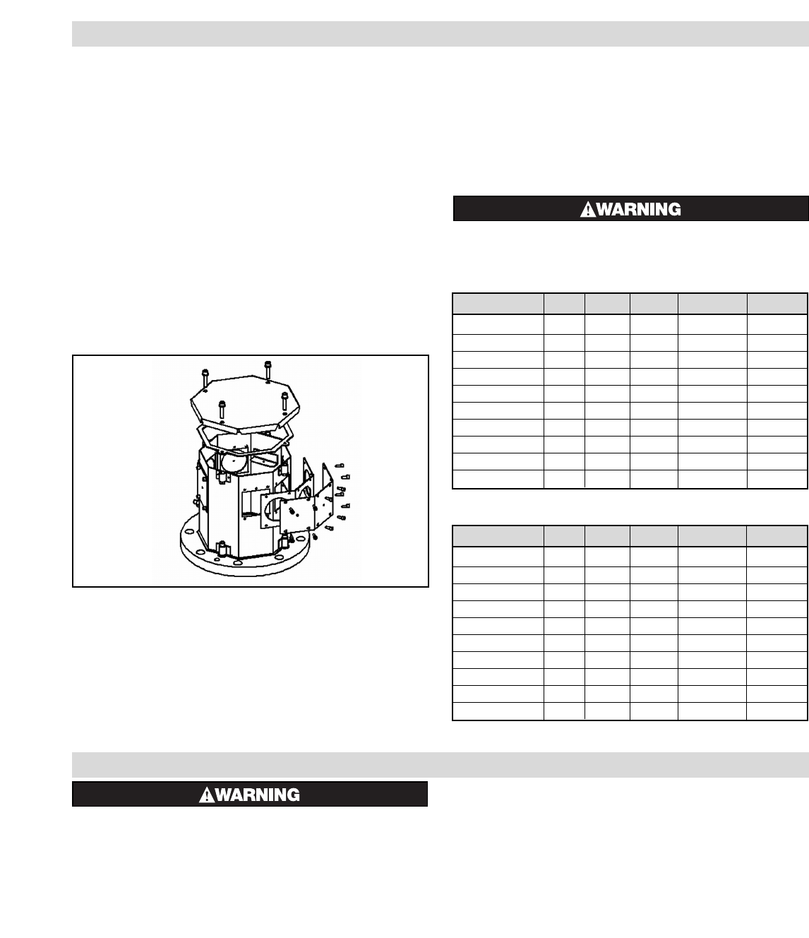
The Moisture Resistant (E4) Housing offers several conve-
nient options for conduit wiring & location. The housing is
equipped with two removable service entrance plates for installa-
tion of wiring. Any or all of the six sides can be used for wiring
locations. Refer to exploded view drawing. The housing can also
be rotated (by removal from flange) to allow for more position
possibilities. To install service entrance holes, simply remove the
side Allen screws and use the centering depression to drill the
appropriate size hole. Reinstall the gasket(s), if applicable, and
service entrance plates by tightening the Allen head screws to 4-5
in-lbs. The 'Octobox' style of housing can be removed for ease of
access to element bussing or to better locate the power conduit(s)
entry point. To accomplish, simply remove the Allen-head screws
on the outside of the housing. When reinstalling, be sure to prop-
erly align gasket, if applicable, and tighten to 40-50 in-lbs.
Tip for Reinstalling Gaskets:
Place Allen Head screws through metal covers and gentle
push gasket hole over the threaded screw. This will allow the gas-
ket to stay in place while tightening the cover.
Wiring Entrance Locations - Explosion Resistant Housing
Only (E2 Option)
The Explosion Resistant (E2) Housing features dedicated
conduit connection sizes and locations for NPT installation of con-
duit. Wiring installation must be in accordance with Hazardous
Area requirements. The use of EYS seals or rigid conduit may be
required. Please consult with the local inspection authority.
Maximum Temperatures
Safe operation in a hazardous location requires the maximum
operating temperatures of all exposed surfaces of the heater
including temperatures on the outside of the vessel, piping,
flanges, screw plugs, enclosures and other heat conducting parts be
limited. The flammable liquids, vapors or gases present determine
the maximum surface temperature permitted in any hazardous
location. The end user or purchaser of the electric heating equip-
ment is responsible for determining the proper classification of an
area and for providing Chromalox with hazardous area specifica-
tions and requirements for proper equipment design. (NEC and
IEC provide guidelines for evaluating and classifying hazardous
locations.)
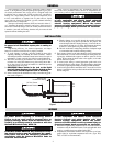
An approved liquid level control or overtemperature
control must be installed to deenergize the heater if
the liquid level drops below the top of the heater.
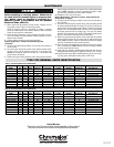
Heater kW Volts Phase Total Amps Circuits
LTFX-125-004E4 4 480 3 4.8 1
LTFX-128-008E4 8 480 3 9.6 1
LTFX-1212-012E4 12 480 3 14.5 1
LTFX-2212-024E4 24 480 3 28.9 1
LTFX-3212-036E4 36 480 3 43.4 1
LTFX-2325-060E4 60 480 3 72.3 1
LTFX-3325-090E4 90 480 3 108.4 3
LTFX-4325-120E4 120 480 3 144.5 2
LTFX-6325-180E4 180 480 3 216.8 3
LTFX-8325-240E4 240 480 3 289.0 4
Heater kW Volts Phase Total Amps Circuits
LTFX-125-004E2 4 480 3 4.8 1
LTFX-128-008E2 8 480 3 9.6 1
LTFX-1212-012E2 12 480 3 14.5 1
LTFX-3210-024E2 24 480 3 28.9 1
LTFX-3215-036E2 36 480 3 43.4 1
LTFX-3225-060E2 60 480 3 72.3 1
LTFX-4225-090E2 90 480 3 108.4 2
LTFX-8215-120E2 120 480 3 144.5 2
LTFX-9220-180E2 180 480 3 216.8 3
LTFX-12225-240E2 240 480 3 289.0 4
Table B – E2 Wiring Information
Table A – E4 Wiring Information
OPERATION
FIRE HAZARD. To avoid possible damage to the
heater, do not energize until the tank is filled with
fluid. Recommended fluid level is 2” above the heater
tube or pipe.
1. Do not operate heaters at voltages in excess of that stamped on the
heater, since excess voltage will shorten heater life.
2. Heaters should not be operated in environments with factors that
can destroy the electrical insulating characteristics of the ceramic
insulators. Foreign contaminants can create leakage (shock) haz-
ards, permanent heater damage, or cause heater failure and there-
fore should be avoided.
For initial operation and tuning the control scheme:
1. Turn the master circuit breaker off and open the control box door.
2. Set the indicating temperature control at the desired temperature
and the over-temperature cutout at 50°F above this temperature.
3. Interlock the liquid level control with the cutout device.
4. Close the control box door and turn the circuit breaker on. To ener-
gize the heater circuits, turn the on-off selector switch to the “on”
position.