


OPTIONAL EQUIPMENT
Temperature Indicators (Suffix “D”)
(FXTH Heater Assembly and Control Center will have
suffix "D" e.g. FXTH-11206D, WCG15-213D)
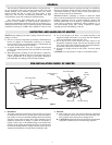
MOUNTING
Temperature indicators are balanced for accurate reading in a normal
vertical position unless specified otherwise. All pyrometers labeled
"shielded meter" may be used in any type of panel with little or no
effect on calibration. Those labeled "non-magnetic" must be used
only on aluminum, plastic, wood or other non-magnetic panels. They
will read low if mounted in a steel panel. Pyrometers which are
labeled "magnetic" are intended for installation on steel panels. A
steel compensating ring is normally supplied where panel material is
not specified. Discard the ring when mounting on a steel panel. If the
pyrometer is used on a non-magnetic panel, the steel ring must be
used. Be sure the slit in the ring is at the top of the meter barrel and
the ring is pushed as far forward as it will go.
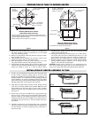
THERMOCOUPLE SELECTION AND CALIBRATION
Each pyrometer is marked on the dial with the type of thermocouple
and the total external resistance for which it is calibrated. Use of any
other type of thermocouple or one with a higher resistance than
marked will result in incorrect readings. (Type J thermocouples are
normally used.) All standard pyrometers are calibrated for 10 ohms
external thermocouple resistance and are provided with a 10 ohm cal-
ibrating resistor bobbin. (Non-standard pyrometers are usually cali-
brated for the specific external resistance ordered and no resistor bob-
bin is supplied.) This resistor bobbin must be adjusted so the total
resistance of the thermocouple and the bobbin add up to 10 ohms in
order to maintain calibration accuracy. Therefore, for a 5 foot, 20
gauge, iron-constantan thermocouple, the resistance of the thermo-
couple would be approximately 1.75 ohms and this resistance must be
subtracted from the calibrating bobbin. Each turn of the wire on the
resistor bobbin represents 0.5 ohms and for this example, 3-1/2 turns
would be removed. The total resistance of the thermocouple plus the
resistor bobbin would then add up to 10 ohms. For other values of
thermocouple resistance, simply remove more or less turns to adjust
for the total value of external resistance marked on the pyrometer
dial.
It is very important the resistor wire be properly soldered after
adjusting.
NOTE: When Thermocouples with external resistance higher than 10
ohms will be used, a special pyrometer will be required. The use of
other than thermocouple wire for leads or extensions may result in
improper ambient compensation.
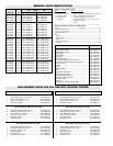
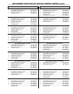
ABBREVIATED TABLE OF THERMOCOUPLE RESISTANCE
The table lists the resistance in ohms per pair-foot for various types
of commonly used thermocouples for a number of different gauges of
wire. By using this table, it is necessary only to measure the length of
the thermocouple, knowing the type and gauge, to determine its
approximate resistance. (Actual measurement of the thermocouple
resistance is preferred to using the table.)
8 .0215 .0184 .0365
10 .0341 .0293 .0580
12 .0542 .0466 .0922
14 .0863 .0741 .1470
16 .1370 .1180 .2330
18 .2180 .1870 .3710
20 .3570 .2980 .5900
22 .5510 .4690 .9370
24 .8770 .7530 1.490
26 1.390 1.200 2.370
28 2:220 1.910 3.770
30 3.520 3.030 5.980
Ohms Per Pair - Foot
Iron/Constantan Copper/Constantan Chromel/Alumel
Gauge B & S (Type J) (Type T) (Type K)
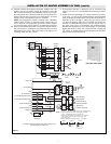
CHROMALOX TYPE TMC 7-DAY TIMER
TMC 7-day Calendar, Electric Dial Timer is used to provide auto-
matic start-up/off-on control of large tank heaters or could be set up
for non-peak operation. Standard features: 7-day calendar dial per-
mits different on/off schedules on different days of week. 2 to 14
replaceable trippers for up to 4 on/off operations per day, up to 28
on/off operations per week. 3 hour minimum on or off time; 21 hour
maximum on or off time. Independent 4-pole design allows SPST,
DPST, SPDT, switching. Manual on/off lever transfers switch opera-
tion without disturbing daily or weekly preset schedule. Heavy duty
synchronous motor suitable for operation between -40°F and +140°F.
Switch slider bar assures positive switching. Heavy duty terminals
accommodate up to AWG No.8 wire.
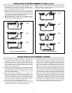
OPERATION
“Off” Setting - de-energizes the entire zone control circuit, thus de-
energizing all heating-cooling equipment in the zone. This setting can
be used for extended summer shutdowns, etc.
“Automatic” Setting - allows the Day-Night Clock Panel to cycle
the control system according to the program clock dial tripper set-
tings.
To Set Trippers - Refer to picture for typical setup of a Seven Day
Program. Two trippers must be used for each day; an “A” tripper for
switching from “Night Setback” to “Day Operation” and a “B” trip-
per for switching from “Day Operation” to “Night Setback”.
CAUTION: To set the correct day and time at beginning of initial
start-up, ROTATE THE PROGRAM CLOCK DIAL CLOCKWISE
ONLY. DO NOT ATTEMPT TO TURN POINTER!
Adjusting and Maintenance of Time Switch:
1. Periodically check trippers to insure that they are tightly fastened
to Program Clock dial. CAUTION: TIGHTEN TRIPPERS WITH
FINGERS ONLY!
2. Rotate Program Clock dial CLOCKWISE one hour in Spring to
adjust for daylight saving time (in areas where required). In Fall,
carefully rotate clock dial CLOCKWISE approximately one full
turn to reset at correct day and time for standard time. Check all
trippers to insure they have not moved during rotation.
3. The Program Clock motor is permanently lubricated. Lubrication
of other parts is not required.
4. The Program Clock switch contacts are factory set and need no
field adjustment.
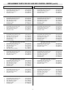
4 Pole
TMC71 311-057070-001 Seven Day 120 2 N.O. 40
2 N.C.
Renewal Volts
Model Part No. Operation 60 Hz Switch Amps
7