


GENERAL
The Chromalox Unitary Electric Immersion Heater, Type RST
or RSTO, is a thoroughly engineered pretested package designed
to give years of service vitrually maintenance free and shipped
ready for installation in storage tank. They provide low watt
denisty heating over a large heating surface with precise tempera-
ture control for such materials as asphalt, fuel oil, pitch and tar, liq-
uid sugar, lube oils, linseed oil, and many other heat sensitive
compounds.
The heating elements, either metal sheath (RST) or open coil
(RSTO) are housed in 3” Schedule 40 carbon steel pipes which are
welded into the tank adaptor box. Once the Unitary Immersion
Heater is welded into your tank, the heating elements are remov-
able without draining the tank.
The control panel contains a master circuit-breaker which is
safety-interlocked so the door cannot be opened when the power is
on, two contactors, a two-step indicating thermostat with the tem-
perature range of 50 to 400°F*, over-temperature cutout with man-
ual reset, control relay, selector switches, pilot lights, and a 120V
control circuit transformer.
*Optional ranges available are 50 to 300°F or -20 to 120°F.
WIRING
INSTALLATION
DANGER: Hazard of Explosion or Fire. The tank
must be purged of all flammable vapors prior to
cutting or welding.
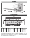
1. Select a location for this installation according to the following:
A. Heating elements are removable thru the lower half of the
control enclosure but adequate room must be provided for
this purpose. This removal length for the RST would be
equal to the length “B” dimension as tabulated in the
Specifications Table 1. The element removal length for the
RSTO is 3 foot since it can be bent on a 12” radius.
B. The control enclosure should not be located where it will be
in direct sun light or be affected by any other heating equip-
ment in the area.
2. Cut a rectangular hole in the tank approximately
1
/4” larger than
the adapter box dimensions tabulated on the Specification
Table 1.
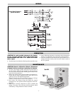
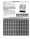
3. Install heater tube supports on 10 foot centers before installing
Immersion Heater assembly (refer to Figure 1). Do not anchor
the heater tubes to the supports as the tubes must be allowed to
expand.
Note: Heater tubes should be level or slightly inclined away
from the control panel.
4. Insert heater tubes and position adapter box as per Figure 1.
5. Weld adapter box to tank insuring that the weld is liquid tight.
6. Tank suction pipe should be mounted at least 2” above the level
of the heaters. A separate line can be provided to drain tank
after heaters have been de-energized.
CAUTION: Hazard of Electric Shock. The Unitary
Immersion Heater must be grounded using ground-
ing means provided in the control box and employ-
ing wiring in accordance with National Electrical
Code.
1. This heater assembly is completely prewired. The only wiring
necessary is the terminals L1, L2, L3 on the main circuit break-
er and the grounding lug in the control panel.
Note: All electrical connections should be checked and tight-
ened if necessary. These sometimes loosen during transit.
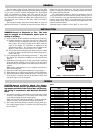
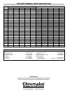
2. The Unitary Immersion Heaters’s internal wiring is per the typ-
ical wiring diagram (Figure 2) with the kW loads being tabu-
lated in Table 2.
kW/Circuit
Model A B
RST (or) RSTO-21915 7.5 7.5
RST (or) RSTO-21920 10.0 10.0
RST (or) RSTO-21925 12.5 12.5
RST (or) RSTO-51530 18.0 12.0
RST (or) RSTO-52038 22.8 15.2
RST (or) RSTO-31518 12.0 6.0
RST (or) RSTO-41524 12.0 12.6
RST (or) RSTO-61536 18.0 18.0
RST (or) RSTO-81545 22.5 22.5
RST (or) RSTO-31720 13.3 6.7
RST (or) RSTO-41726 13.0 13.0
RST (or) RSTO-51732 19.2 12.8
RST (or) RSTO-61740 20.0 20.0
RST (or) RSTO-71848 27.4 20.6
RST (or) RSTO-31922 14.7 7.3
RST (or) RSTO-41930 15.0 15.0
RST (or) RSTO-51936 21.6 14.4
RST (or) RSTO-61945 22.5 22.5
RST (or) RSTO-72156 32.0 24.0
RST (or) RSTO-32024 16.0 8.0
RST (or) RSTO-42336 18.0 18.0
RST (or) RSTO-52548 28.8 19.2
RST (or) RSTO-62660 30.0 30.0
RST (or) RSTO-72672 41.1 31.9
Figure 1 — Typical Installation in Dished Head Tank
Table 2
-2-