


MOUNTING
Note: Do not mount control where it will be subject to vibration,
shock, grease, dust, lint or corrosive vapors. Do not mount adja-
cent to a large magnetic contactor, as vibration and shock will
cause thermostat to interact erratically – resulting in chattering of
the contactor.
CAUTION: Do not twist or uncoil the coiled element on top of the
case of the WR-90.
The proper location of a heavy duty room thermostat is important
to assure good performance.
1. Locate where air circulates freely.
2. Never install on or near outside wall.
3. Keep away from windows or doors.
4. Do not locate too close to strong light or other false source of
heat, such as sunlight, steam lines, etc.
5. If electrical conduit leads into cooler or warmer room, plug up
space around wires in the conduit with rock wool.
WIRING
CALIBRATION
CAUTION: Hazard of Electric Shock. Disconnect all
power before wiring or servicing this control.
1. Electric wiring to heater must be installed in accordance with
National Electrical Code and with local codes. WARNING:
Use copper conductors only.
Connect wires according to wiring diagrams (Figures 1 and 2).
Note: Electrical connections should be made with generous
loops of wire – approximately 6” per lead.
Note: If load amperage or voltage rating exceeds switch rating,
a contactor must be used. Contactor and wiring to be supplied
by customer. (See Figure 2)
CAUTION: Hazard of Electric Shock. Extreme care
should be exercised during calibration adjustments
because of shock hazard due to exposed electrical
terminals.
WR-80 thermostats are accurately calibrated at the factory so
the dial setting correctly indicates the temperature at which the
contacts open on temperature rise. If, as a result of damage in tran-
sit or for other reasons the room temperature differs appreciably
from the dial setting, the calibration may be adjusted as follows:
1. Note temperature on thermometer.
2. Set dial at highest temperature.
3. Turn dial slowly to lower temperature and stop when thermo-
stat contacts open.
4. Loosen screw at bottom of thermostat and remove thermostat
from mounting plate.
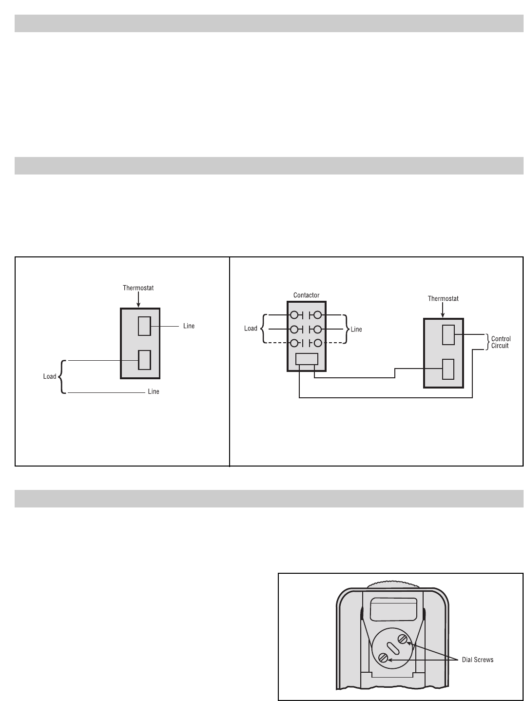
5. On back of thermostat, loosen two dial screws (Figure 3).
Carefully turn the dial only to correct temperature setting as
indicated by thermometer. Be sure the thermostat shaft is not
moved during this operation.
6. Tighten the dial screws and replace thermostat.
Figure 3
Figure 1 — Single phase loads when load does not exceed
rating of thermostat.
Figure 2 — Single phase loads when load exceeds rating of thermostat and
three phase loads.