


ELECTRIC SHOCK HAZARD. Disconect all power to
heater before installing or servicing thermostat.
Failure to do so could result in personal injury or
property damage. Thermostat must be installed by a
qualified person in accordance with the National
Electrical Code, NFPA 70.
1. Electric wiring to heater must be installed in accordance with
local and National Electrical Codes.
CAUTION: Use copper conductors only.
2. Entrance for wiring is provided by two
1
/2” conduit holes in end
of base plate.
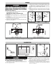
3. If control is a “KC” model (Knob Cover), remove knob cover
as in Figure 5.
4. Set thermostat knob to OFF position and then remove knob by
lifting knob from shaft. (See Figure 6)
5. Loosen two screws from end of base plate and remove ther-
mostat cover (see Figure 7).
6. Connect wires according to wiring diagrams (Figures 8 thru
12). Note: Electrical connections should be made with gener-
ous loops of wire — approximately 6” per lead.
7. Replace cover, tighten screws, replace dial knob and dial knob
cover.
8. Note: If load amperage or voltage rating exceeds switch rating,
a contactor must be used. Contactor and wiring to be supplied
by customer.
WIRING
CALIBRATION
ELECTRIC SHOCK HAZARD. Disconnect all power
before attempting to calibrate thermostat. Failure
to comply could result in personal injury.
These controls are factory calibrated to the range indicated on
the control adjustment knob.
If calibration is required, either one of two methods may be
followed.
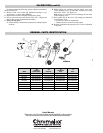
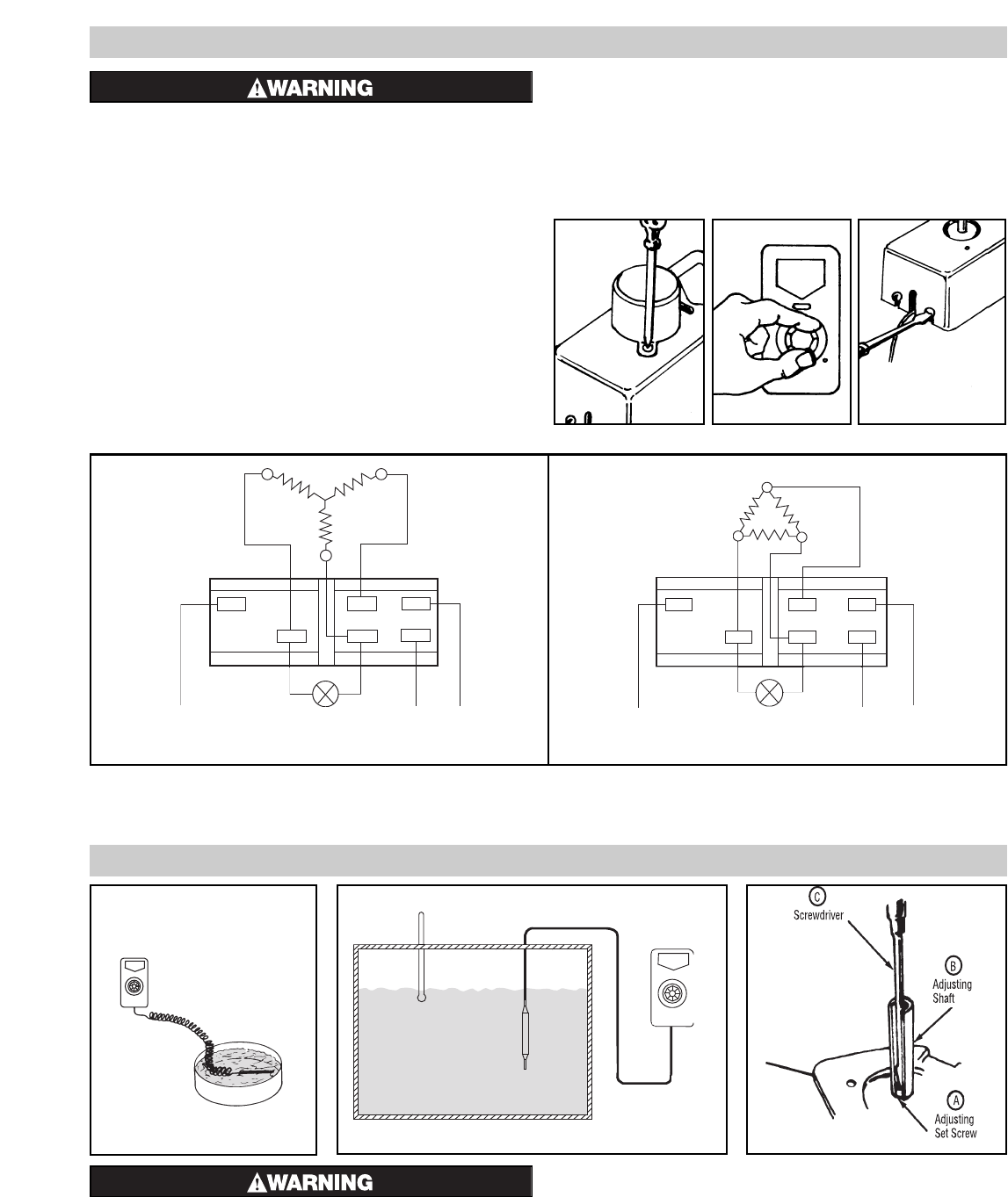
1. If accurate measurement standards are not available, the ther-
mostat can readily be adjusted to a known temperature stan-
dard such as boiling water (212°F) (see Figure 10).
2. With the aid of an accurate thermometer or other temperature
measuring device, recalibration may be performed within the
process as in Figure 11.
12
3
4
56
L1 L2
L3
Pilot Light
(Optional)
Note: One line (terminals 5-6) is controlled by the dial and is on continually whenever the dial is moved from the off position. The other
two lines are thermostatically controlled and cycle with the rise or fall in temperature.
Thermometer
Load (Tank, vat, die or platen)
Figure 10
Figure 12Figure 11
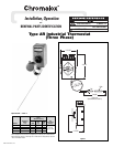
Figure 8 — Three-Phase “Y” Load
1
23
4
5
6
Pilot Light
(Optional)
L1
L2
L3
Figure 9 — Three-Phase Delta Load
Figure 5
Figure 6 Figure 7