


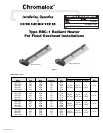


3
WIRING
ELECTRIC SHOCK HAZARD. Disconnect all power
before installing or servicing heater. Failure to do
so could result in personal injury or property dam-
age. Heater must be effectively grounded in accor-
dance with the National Electrical Code, NFPA 70.
All electrical wiring must be done by a qualified
person in accordance with National Electrical Code
(NEC) and meet all state and local regulations.
1. Use heater only at the voltage specified on the nameplate.
2. Branch circuit wire for connection to heater must be at least
90°C wire. Use copper conductors only.
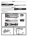
3. The heater connection points are located in the gasketed termi-
nal enclosure. To remove cover, remove 4 screws on the cover.
Remove the cover to expose wiring connection points.
4. A green ground terminal is provided in the bottom of the enclo-
sure. The ground wire should be connected before other con-
nections are made.
5. Refer to Table 1 for proper entrance wiring size.
6. Heater can be wired with rigid or flexible conduit.
Grill Kit Selection Guide
Model Volts Watts Optional Grill Kit
RBC-1101 120 1000
RBC-1108 208 1000
RBC-1102 240 1000 168-053169-085
RBC-1107 277 1000
RBC-11034 347 1000
RBC-1151 120 1500
RBC-1158 208 1500
RBC-1152 240 1500 68-053169-086
RBC-1157 277 1500
RBC-11534 347 1500
RBC-1208 208 2000
RBC-1202 240 2000
68-053169-087
RBC-1207 277 2000
RBC-12034 347 2000
RBC-1258 208 2500
RBC-1252 240 2500
68-053169-088
RBC-1257 277 2500
RBC-12534 347 2500
MAINTENANCE
ELECTRIC SHOCK HAZARD. Disconnect all power
before servicing or replacing heating elements.
The reflectors should be kept clean to obtain the maximum
radiant output.
Element Replacement
1. Remove Terminal Box Cover.
2. Disconnect lead wires from heater terminals and disengage box
from conduit /cable fitting.
3. Remove safety grills (if installed).
4. Loosen (2) 3/8” nuts from the terminal box bracket located on
the back of the heater and slide the entire heating element
assembly out of the reflector assembly.
5. Remove bulkhead fitting nut and washers.
6. Remove failed element and replace with a new element.
7. Place gasket on the bulkhead fitting and insert terminals and fit-
ting into the element hole in the terminal box.
8. Place washer and nut on the bulkhead fitting and tighten.
9. Reassemble by following the reverse procedures (steps 4
through 1)
Replacement Parts
Model Volts Watts Element
RBC-1101 120 1000 322-074905-143
RBC-1108 208 1000 322-074905-144
RBC-1102 240 1000 322-074905-145
RBC-1107 277 1000 322-074905-146
RBC-11034 347 1000 322-074905-147
RBC-1151 120 1500 322-074905-148
RBC-1158 208 1500 322-074905-149
RBC-1152 240 1500 322-074905-150
RBC-1157 277 1500 322-074905-151
RBC-11534 347 1500 322-074905-152
RBC-1208 208 2000 322-074905-153
RBC-1202 240 2000 322-074905-154
RBC-1207 277 2000 322-074905-155
RBC-12034 347 2000 322-074905-156
RBC-1258 208 2500 322-074905-157
RBC-1252 240 2500 322-074905-158
RBC-1257 277 2500 322-074905-159
RBC-12534 347 2500 322-074905-160
IMPORTANT INSTRUCTIONS
When using electrical appliances, basic precautions should
always be followed to reduce risk of fire, electric shock and injury
to persons, including the following:
1. Read all instructions before using this heater.
2. This heater is hot when in use. To avoid burns, do not let bare
skin touch hot surfaces. Keep combustible materials, such as
furniture and papers at least 7 feet from the front of the heater.
3. Always disconnect heater when not in use.
4. Do not use outdoors.
5. Connect to properly grounded outlets or building ground.
6. This heater has hot surfaces. Do not use it in areas where gaso-
line, paint or flammable liquids are used or stored.
7. Use this heater only as described in this manual. Any other use
not recommended by the manufacturer may cause fire, electric
shock or injury to persons.
8. In order to prevent equipment damage, protect with a ground
fault device such as Chromalox STAR-GF series monitor.
9.
SAVE THESE INSTRUCTIONS