


3
OPTIONAL ACCESSORIES
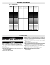
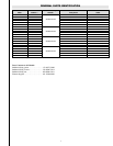
Chromalox STAR series radiant heaters can be field modified
by adding optional kits. Refer to Chart A to select the proper kit.
Portable Cart Kit
The portable cart kit can be used to convert a fixed overhead
unit into a portable heating device where a fixed installation is not
required. This kit includes wheels, legs, handle, grill(s), baffle (if
reqd) and all of the necessary hardware to complete the modifica-
tion. See instruction bulletin PG435 for details.
Grill Kit
The grill kit consists of one (1.5, 2, 4.5 and 6 kW) or 2 grill sec-
tions (13.5kW) and hardware to protect personnel from coming
into contact with hot radiant heating elements. See instruction bul-
letin PG437 for details.
Disconnect Kit
The disconnect kit consists of a complete assembly consisting
of a disconnect switch (3 Pole), power terminal block and all hard-
ware to complete the installation. This kit can be mounted to both
the fixed, overhead heater or the portable heater; see instruction
bulletin PG436 for details.
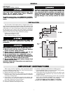
Hanger Kit
Hanger kits include 24 feet of chain and four S hooks to mount
the unit in a fixed overhead position using the universal mounting
brackets included on the heater. This kit allows installation dis-
tances from the ceiling of 2 feet to 6 feet. See installation diagram
Fig. 4 on page 2.
Cord Kits (Portable Only)
Cord kits consist of 25 feet of 90°C cable and a right angle cord
fitting which can connect directly to the heater terminal box or dis-
connect switch (if used). See installation bulletin PF491 for details
Tip Over and Ground Fault Kits
STAR TIP Series Kit attaches to portable heater and de-ener-
gizes the heater in the event it is tipped over.
STAR-GF Series Kit mounts to wall that de-energizes heater
prior to element failure.
STAR-TG Kit combines the tip over and ground fault feature for
portable heaters. See installation bulletin PG436.
WIRING
ELECRIC SHOCK HAZARD. Disconnect all power
before installing or servicing heater. Failure to do so
could result in personal injury or property damage.
Heater must be effectively grounded in accordance
with the National Electrical Code, NFPA 70.
All electrical wiring must be done by a qualified per-
son in accordance with National Electrical Code (NEC)
and meet all state and local regulations.
1. Use heater only at the voltage specified on the nameplate.
2. Branch circuit wire for connection to heater must be at least 90°C
wire. Use copper conductors only.
3. The heater connection points are located in the gasketed terminal
enclosure. To remove cover, remove 4 screws on the cover.
Remove the cover to expose wiring connection points.
4. Agreen ground terminal is provided in the bottom of the enclosure.
The ground wire should be connected before other connections are
made.
5. Refer to Table 1 for proper entrance wiring size.
6. Heater can be wired with rigid or flexible conduit.
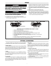
7. All 3 element heaters are factory pre-wired for 3-phase delta oper-
ation. Some units can be converted to single phase operation by
changing the wiring. Refer to Table 1 for those heaters that can be
converted to single phase. The appropriate wiring diagram (Figure
3) is also located on the bottom of the enclosure.
INSTRUCTIONS FOR FIELD CONVERSION FROM 3 PHASE TO 1 PHASE:
1. Remove nuts from all terminals.
2. Remove all pigtail leads and hat shaped buss bar.
3. Remove end of leadwire on terminal 5 and slip onto terminal 4.
4. Remove leadwire attached to instruction sheet and connect between terminals 4 and 6.
5. Install hat shaped buss bar between terminals 3 and 5.
6. Place pigtail lead marked “L1” on to terminal 2 and pigtail lead marked “L2” on to terminal 6.
7. Install nuts.
8. Connect entrance wiring to pigtail leads “L1” and “L2”. Connect ground to screw provided.
9. Inspect to make sure wiring is per “Single Phase Wiring” above.