


WARNING: Hazard of Electric Shock. Disconnect all
power before servicing heater.
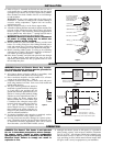
TO REMOVE HEATING ELEMENT
1. Remove terminal cover screws and terminal cover.
2. Disconnect heating element from electrical leads at both ends.
3. Remove screws from porcelain terminal blocks.
4. Remove element support clips and secondary insulating bush-
ings (where used).
5. Lift out element.
TO INSTALL ELEMENT
Observe instructions for removing element and proceed in
reverse fashion. Be sure to replace secondary insulating bushings
and support clips (where used).
WARNING: For your own safety —
Before energizing this heater:
1. Be sure all electrical connections are tightly made. Hold termi-
nal with pliers when tightening screw.
2. Be sure that all conductors are properly insulated.
3. Be sure that all element assemblies have been properly
replaced, and that secondary insulation bushings and support
clips (where used) have not been omitted.
CARE OF REFLECTORS
Reflectors should be cleaned periodically. A mild soap and
water solution or fine cleaning powder is best although more dras-
tic means may be required if reflectors are badly soiled by chemi-
cal or other deposits. The reflector is aluminum. DO NOT use
alkali cleaners since alkalies will dull reflector. Mild non-alkaline
cleaners, such as used for scouring kitchen sinks, amy be used.
Reflectors are replaceable and may be purchased from Chromalox.
MAINTENANCE
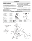
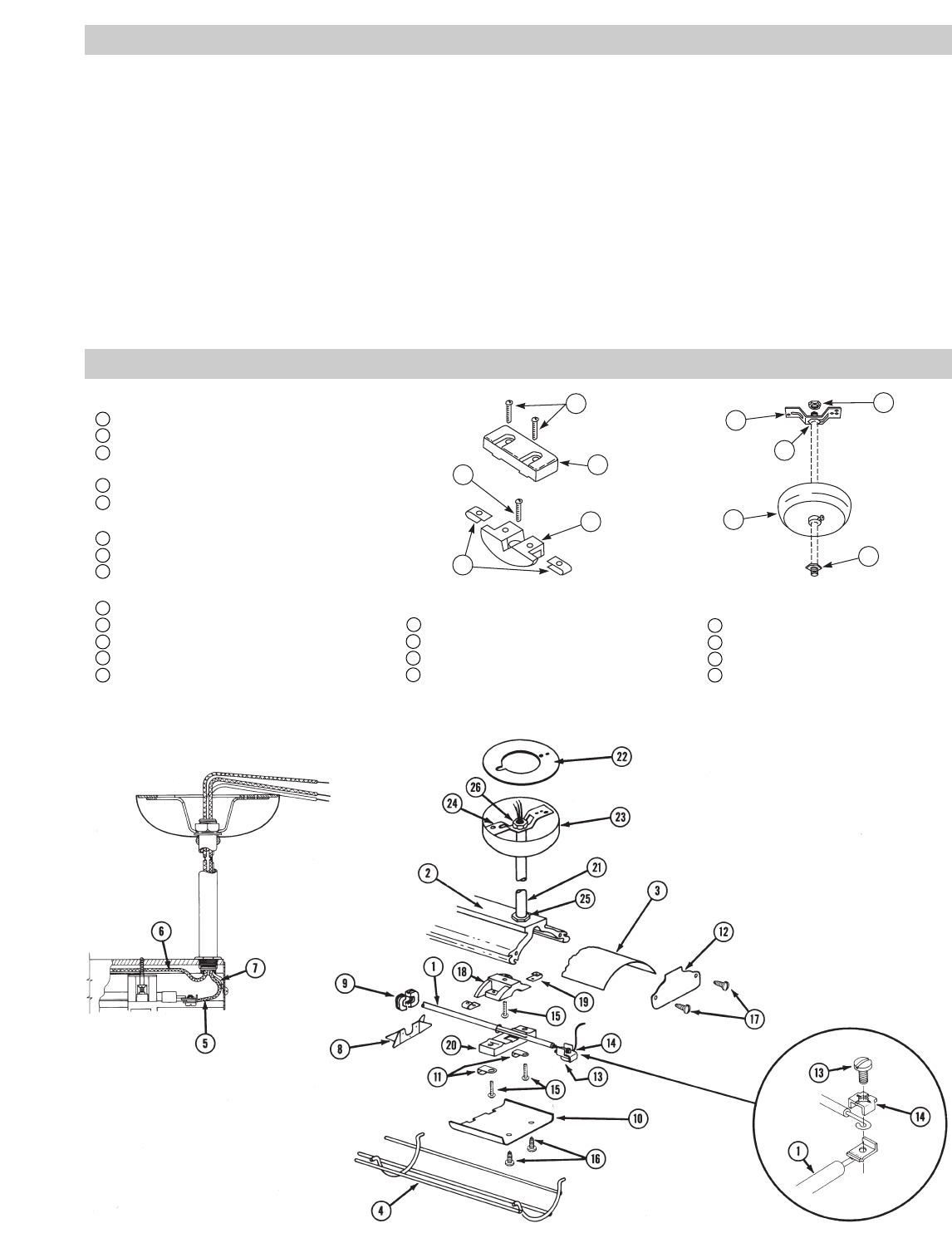
RENEWAL PARTS IDENTIFICATION
24
25
23
26
25
15
20
15
18
19
PARTS COMMON TO ALL HEATERS
10 Terminal Cover . . . . . . . . . . . . . . . .306-014405-001 (2)
11 Terminal Cover Clip . . . . . . . . . . . .056-014401-002 (4)
12 End Plates . . . . . . . . . . . . . . . . . . .220-014462-004†
220-014462-002
13 Terminal Screw . . . . . . . . . . . . . . .248-002793-001 (2)
14 Saddle Clamp . . . . . . . . . . . . . . . . .238-026539-001 (2)
MISCELLANEOUS HARDWARE
15 #8 x 1” Lg. . . . . . . . . . . . . . . . . . . .248-075519-095 (6)
16 #8 x
3
/8” Lg. . . . . . . . . . . . . . . . . . .248-075519-080 (4)
17 #8-32 x
3
/8” Lg. . . . . . . . . . . . . . . . .248-075414-051 (4)
MISCELLANEOUS PARTS
18 Terminal Block . . . . . . . . . . . . . . . .303-016367-001 (2)
19 Speed Nuts . . . . . . . . . . . . . . . . . .272-048153-005 (4)
20 Terminal Block . . . . . . . . . . . . . . . .303-014326-001 (2)
21 Conduit . . . . . . . . . . . . . . . . . . . . .069-017920-001 (2)
22 Cover Plate, Box . . . . . . . . . . . . . . .220-017915-001 (1)
TERMINAL BLOCK SET
168-016585-001 consists of the following:
18
Terminal Block . . . . . . . . . . . . . . . .303-016367-001 (2)
19 Speed Nuts . . . . . . . . . . . . . . . . . .272-048153-005 (4)
20 Terminal Block . . . . . . . . . . . . . . . .303-014326-001 (2)
15 Screws — #8 x 1” Lg. . . . . . . . . . .248-075519-095 (6)
HANGER KIT
168-050202-001 (2) consists of the following:
23
Canopy, with set screw . . . . . . . . . . . . . . . . (1)
24 Hanger Bracket . . . . . . . . . . . . . . . . . . . . . . (1)
25 Flat Locknut . . . . . . . . . . . . . . . . . . . . . . . . (2)
26 Hex Nut (Spherical) . . . . . . . . . . . . . . . . . . . (1)
† Indicates stamped end plate with voltage, wattage, etc.
Note: Part numbers suffixed by a number in ( ) indicates the quantity of the same part number used.
Figure 6
Figure 7
Figure 8
Figure 9