


-2-
INSTALLATION (cont’d.)
ELECTRIC SHOCK HAZARD. Disconnect all power
before installing or servicing heater. Failure to do
so could result in personal injury or property dam-
age. Heater must be installed or serviced by a
qualified person in accordance with the National
Electrical Code, NFPA 70.
ELECTRIC SHOCK HAZARD. Any installation
involving electric heaters must be performed by a
qualified person and must be effectively grounded
in accordance with the National Electrical Code to
eliminate shock hazard.
1. Electrical connection to the Radiant Heater is made through
two openings tapped for 1/2” connector. Openings are in the
top of the extruded heater housing, one near each end.
2. Access to Radiant Heater terminals is obtained by removing
the two screws in each of the terminal box covers.
3. Wiring should be run in flexible or rigid metal conduit and
must be installed in accordance with the requirements of the
National Electric Code and such other local requirements as
may be applicable.
4. Wires supplying power to heating element terminals shall have
insulation rated for 150°C minimum.
High Temperatures will oxidize copper. Use only nickel-
plated copper wire for supplying power to heater. Do not
use aluminum conductors.
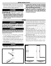
5. A sufficient length of high temperature wire (not less than 12”
should extend from heater terminals to a remote connection
box whose location involves normal room temperatures there-
by permitting use of normal electrical wiring to that point.
6. Leave loop of wire in heater terminal box to allow for expan-
sion movement of heating elements.
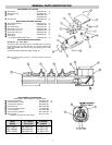
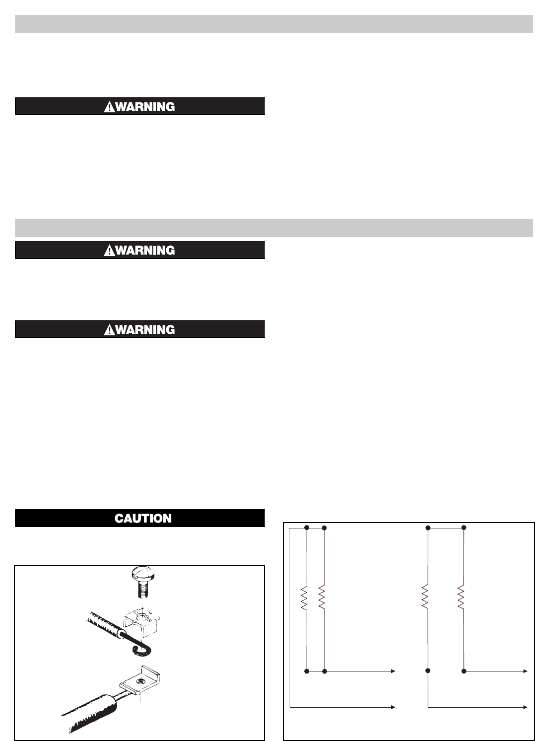
7. Assemble terminal, screw, saddle clamp and wire as shown in
Figure 3.
8. Hold terminal with pliers and tighten the terminal screw
securely with a screwdriver.
9. Single End. Parallel Wiring (Fig. 4A) Power wiring enters
heater through either of the 1/2” tapped openings in heater
housing. Wiring to opposite end is conveyed through wire-way
provided behind integral reflector in housing extrusion. High
temperature wire must be used; maximum wire diameter (over
insulation) must not exceed 0.224”. Each element must be
rated at applied line voltage.
10. Single End, Series Wiring (Fig. 4B) Power wiring enters
heater through either of the 1/2” tapped openings in heater
housing. Heating element terminals at opposite end are wired
in series. High temperature wiring must be used. Each element
must be rated at 1/2 line voltage.
External series wiring of radiant heater assemblies is not prac-
tical when internal series connections can be made so easily.
WIRING
Single End — Parallel
Figure 4A
Single End — Series
Figure 4B
Figure 3
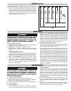
5. Reflector Spacer Sheets —
Where heaters are not mounted side
by side (see Fig. 2), reflector spacer sheets can be used between
heaters. These reflector spacer sheets and companion reflectors
consisting of an extruded aluminum housing with reflector sheet
and mounting clamps are available. Check factory.
FIRE HAZARD: Since Radiant heaters are capable
of developing high temperatures, extreme care
should be taken to:
A. Keep combustible materials at least 6” away
form sides and back of heater housing and its
supporting brackets and spaced far enough in
front of heater (heating element side) so thermal
radiation from the elements will not ignite com-
bustible materials.
B. If combustible materials are being processed,
stoppage of process should initiate immediate
heater shutdown and interception of residual
heat from radiant heaters (use radiation baffles
or move heaters away from work).
C. In the case of solvents of an explosive nature,
ventilation air must be in sufficient volume to
dilute the solvent vapor so that explosive mix-
tures cannot occur, refer to NFPA 86, Standard
for Ovens and Furnaces.