


DIVISION
4
SECTION
RAD
SALES
REFERENCE
DATE
SERVICE REFERENCE
Installation, Operation
and
RENEWAL PARTS IDENTIFICATION
161-048766-001
FEBRUARY, 1987
PG407-3
(Supersedes PG407-2)
Chromalox
®
© 2010 Chromalox, Inc.
Chromalox Type RAD Radiant Heaters
Converting Styles 0, 1, 3 and 3A to 3B
The current Chromalox Style 3B RAD has superseded earlier
Styles 0, 1, 3 and 3A RAD heaters. These instructions are for con-
verting these earlier models to the current Style 3B. This conversion
is necessary because replacement parts for the old models are no
longer available.
The changes involved are primarily in the terminal area as
shown in Figures I, 2 and 3. Match-up one of the Figures with your
heater's terminal arrangement and order the corresponding parts bag
(Figures 4 and 5). If an element or other part listed in Table A (page
3) is necessary, order according to heater housing length and the
voltage and wattage stamped on the element and the heater name-
plate.
For complete installation information for type RAD - Style
3B, request Chromalox Service Reference sheet PG404.
GENERAL
CONVERSION
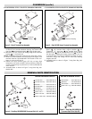
Figure 1 – Style 0 and 1 Terminal Area Assembly
CAUTION: Hazard of electric shock. Disconnect
power before servicing heater.
A. CONVERTING STYLES 0 AND 1 TO
STYLE 3B RADIANT HEATER
1. Completely disassemble heater. Re-use the heating element (if
desired) and the extruded aluminum housing (Fig. 7). Scrap all
the other parts.
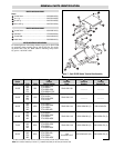
2. Drill #24 (.152" dia.) hole in the back of the extruded housing
, 3" from each end. (See Fig. 7)
3. NOTE: If replacing old element with a new one, omit this step.
Remove wire retaining loops ® (Fig. 6) from the elements and
replace with wire loops fashioned from #15 gage (.072" dia.) or
larger stainless steel wire located 2-1/4” from each end of the
sheath. Other high temperature materials such as nichrome may
be substituted. Braze or tack weld the loops in position.
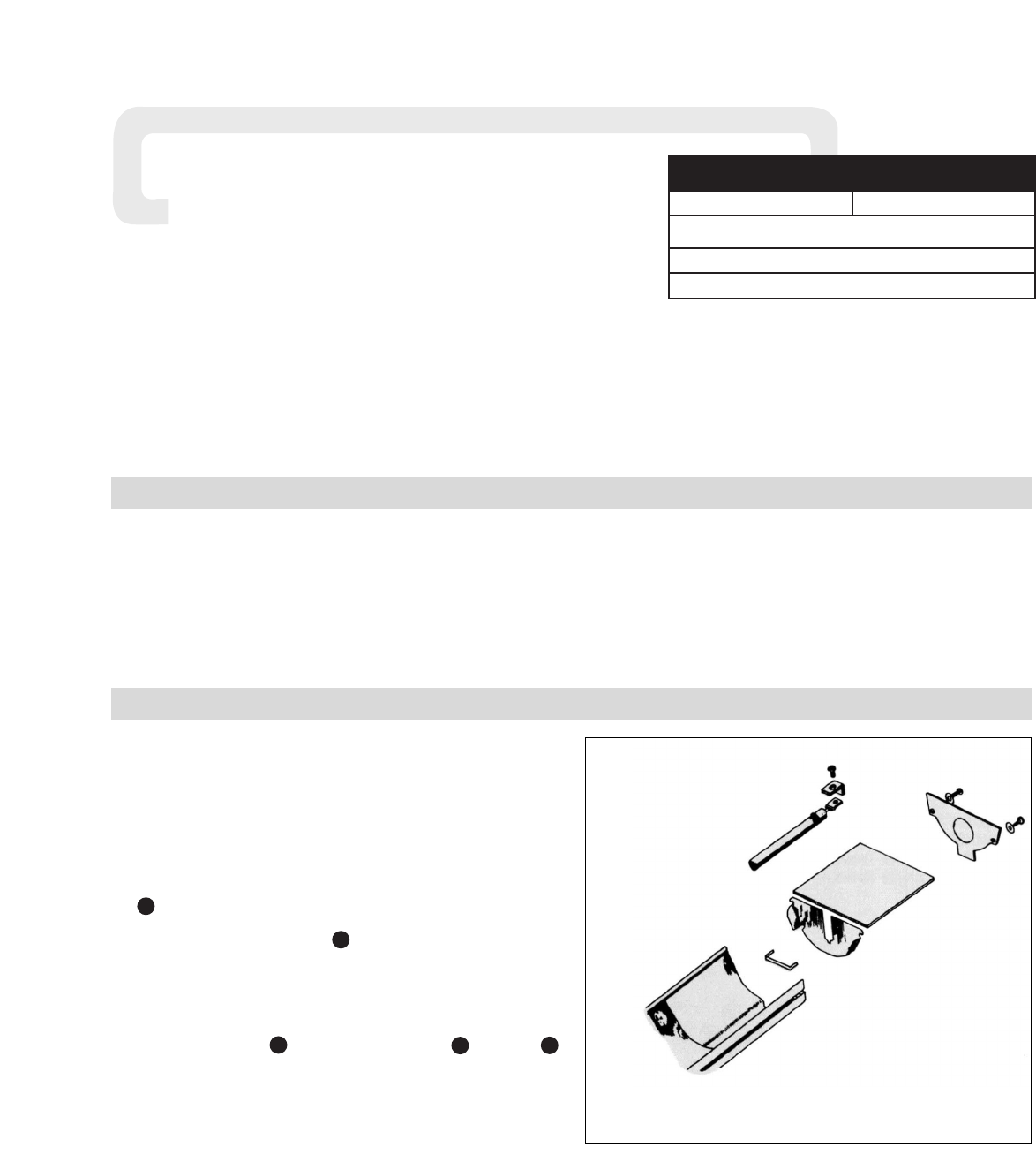
4. Besides the Parts Bag 168-016585-002 (Fig. 4), you will need
insulation bushings ®, element support clips , reflector ®
and element (if required) as listed in Table A, page 2.
NOTE: Quantities of these parts, as well as size of element and
reflector will be determined by the heater housing length of the old
unit.
5. Assemble heater as shown in Figure 7.
A
B
6
7
2