


IMPORTANT
WARNING: Hazard of Shock. Any installation
involving electric heaters must be effectively
grounded in accordance with the National
Electrical Code.
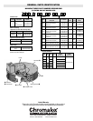
1. Heater should be positioned with junction box facing away
from walls to provide easy access for servicing relay(s) mount-
ed within.
WARNING: Mount the heater for down discharge
only.
2. It is important that 12” minimum dimension shown in Figure 1
be maintained to make it possible for a serviceman to remove
the fan motor, if necessary, without moving the heater from its
mounting.
WARNING: The heater must be mounted at least 7’
above the floor to prevent accidental contact with
the heating elements or fan blade which could
cause injury.
The ceiling structure, the brackets, hangers or chains used to sus-
pend the heater, and the anchoring provisions must be of sufficient
strength to support the total weight of the heater installation (250
pounds for VUH-C-30, 40, 50 plus the weight of the supports).
3. The heater may be mounted to the ceiling by attaching rigid
angle brackets, hangers, or chains to the four mounting holes
on top of the heater case using four
5
/8” bolts (by others). See
Figures 1 and 2.
Note: Brackets, hangers, or chains to support the heater are sup-
plied by the customer.
4. All wiring should be done in accordance with the National
Electrical Code and with local codes by a qualified person as
defined in the NEC.
WARNING: Use copper conductors only.
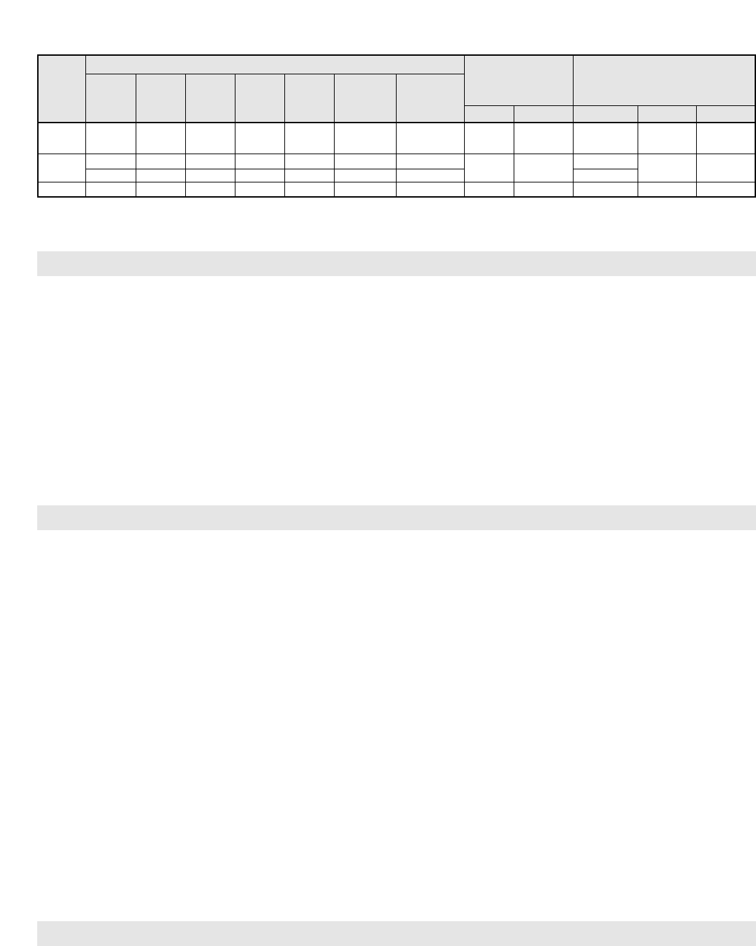
5. Rough-in wiring to heater. See Table 2 for line amperes, rec-
ommended wire size and conduit size.
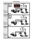
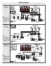
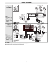
6. Wire heater per wiring diagram supplied with this instruction
sheet.
Note: Power relay(s) are provided as standard on all heaters.
WARNING: Prior to operating the heater, verify that
the fan hub setscrews are tightened and the push-
on clip is secured to assure that the fan blade is
securely fastened to the motor shaft.
7. Carefully inspect the completed installation. Rotate the fan
blade by hand to be sure that it turns freely. Investigate any
binding, rubbing or interference.
WARNING: On Models connected to three-phase
power, fan blade rotation must be checked if the
airflow is not downward. Interchange any two of
the three customer power leads.
8. Air diffusers for deflecting the air are optional. See Instruction
Sheet PF449 for installation instructions.
INSTALLATION
Failure to understand and follow these installation instructions and
the “WARNING” notes therein may result in serious personal
injury from electrical shock, or from the heater falling due to
faulty installation.
WARNING: This heater is not intended for use in
hazardous atmospheres where flammable vapors,
gases, liquids or other combustible atmospheres
are present as defined in the National Electrical
Code. Failure to comply can result in explosion or
fire. For these applications see PDS CXH-EP (PF305).
WARNING: Hazard of Shock. Disconnect all power
before installing heater.
The heater must be mounted at least 7’ above the floor to prevent
accidental contact with the heating elements or fan blade which
could cause injury.
The ceiling structure, the brackets, hangers or chains used to sus-
pend the heater, and the anchoring provisions must be of sufficient
strength to support the total weight of the heater installation (250
pounds for VUH-C-30, 40, 50 plus the weight of the supports).
Prior to operating the heater verify that the fan hub setscrews are
tightened and the push-on clip is secured to assure that the fan
blade is securely fastened to the motor shaft.
On Models connected to three-phase power, fan blade rotation
must be checked. If the airflow is not downward, interchange any
two of the three customer power leads.
First stage of thermostat must be connected to terminals C1 and C2
to insure proper operation of overheat protective devices.
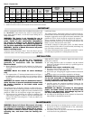
Table 2 – Electrical Data
Power Supply Circuit
Model Line
Motor
Line Wire Minimum
Amps Size No. Conduit
kW Volts Phase (Note 1) (Note 2) Circuits Size † Inrush Sealed Volts H.P. Phase
208 3 44 6 2 1-1/4 208
VUH-C-30 30 240 3 38 8 2 1 104 18 240 1/3 3
480 3 37 8 1 1-3/4 480
VUH-C-40
38.5 240 3 48 6 2 1-1/4
104 18
240
1/3 3
39 480 3 48 6 1 1 480
VUH-C-50 50 480 3 31 8 2 1 104 18 480 1/3 3
Contactor
Holding Coil
Volt Amperes
(Note 3)
1. Includes Fan Motor Amps † Conduit knockout location – top of Junction Box.
2. Use 90°C Wire - Copper conductors only
3. Standard units have two contactors. Units with separate fan motor control use three contactors.
MAINTENANCE
WARNING: Hazard of Shock. Disconnect all power
to heater before servicing or replacing heaters. Do
not attempt to service heater while unit is operat-
ing as there is hazard of electric shock, injury from
operating fan, and burns from hot heating ele-
ments.
1. Before activating for next heating season, vacuum or use com-
pressed air to remove accumulated dust or lint, which other-
wise may restrict proper air flow.
2. Periodically check all electrical connections and retighten to
avoid electrical wiring difficulties.
2