


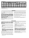
MAINTENANCE
WARNING: Hazard of Shock. Disconnect all power
to heater before servicing or replacing heaters. Do
not attempt to service heater while unit is operat-
ing as there is hazard of electric shock, injury
from operating fan, and burns from hot heating
elements.
1. Before activating for next heating season, vacuum or use com-
pressed air to remove accumulated dust or lint, which other-
wise may restrict proper air flow.
2. Periodically check all electrical connections and retighten to
avoid electrical wiring difficulties.
Note: All fan motors are totally enclosed and internally thermal overload protected.
MOTOR LUBRICATION
Motors in VUH-C-15 through VUH-C-25 have sleeve bearings which are factory lubricated.
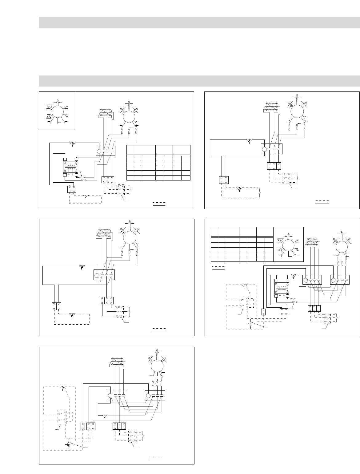
WIRING DIAGRAMS
VOLT
Transformer Color Code Index
PRI XFMR
LEAD CLRS
120V SEC.
LEAD CLRS
24V SEC.
LEAD CLRS
208
240
277
480
H1
BLK
BLK
BLK
BLK
X1
BLK
BLK
BLK
BLK
X2
WHT
WHT
WHT
WHT
X1
YEL
YEL
YEL
YEL
X2
BLU
BLU
BLU
BLU
H2
RED
ORG
BRN
BLK/RED
L1
L1
L2
C1
C1
X1
C2
TB2
XFMR
Fusing
Optional
XFMR
L3
L2
L3
T1
T2
T3
X2
H1 H2
Thermostat
(By Others)
Contactor
To Fuses
Cutout
Elements
Fused Switch
(By Others)
3ø
Power
60 HZ
1
TB1
3
M
2
9
4
6
8
11
5
107
208 - 240V Motor Hook-Up
KTK-4
Customer Wiring
Factory Wire
1
2
3
M
4
6
11
5
8
10
9
7
480V Motor Hook-Up
Figure 3
L1
L1
L2
C1
C1
C2
TB2
L3
L2 L3
T1
T2
T3
Thermostat
(By Others)
Contactor
Cutout
Elements
Fused Switch
(By Others)
3ø
Power
60 HZ
1
TB1
3
M
2
9
4
6
8
11
5
107
208 - 240V Motor Hook-Up
KTK-4
Customer Wiring
Factory Wire
Figure 5
L1
L1
L2
C1
C1
C2
TB2
L3
L2 L3
T1
T2
T3
Thermostat
(By Others)
Control Power
(By Others)
Contactor
Cutout
Elements
Fused Switch
(By Others)
3ø
Power
60 HZ
1
TB1
3
M
2
9
4
6
8
11
5
107
208 - 240V Motor Hook-Up
KTK-4
Customer Wiring
Factory Wire
Figure 4
VOLT
Transformer Color Code Index
PRI XFMR
LEAD CLRS
120V SEC.
LEAD CLRS
24V SEC.
LEAD CLRS
208
240
277
480
H1
BLK
BLK
BLK
BLK
X1
BLK
BLK
BLK
BLK
X2
WHT
WHT
WHT
WHT
X1
YEL
YEL
YEL
YEL
X2
BLU
BLU
BLU
BLU
H2
RED
ORG
BRN
BLK/RED
L1
L1
L2
C1
C4
C1
X1
C2
TB2
TB2
Fan
Heat
XFMR
Fusing
Optional
Optional Heat
Recovery switch
(By Others)
2 PDT
Switch
(By Others)
XFMR
L3
L2 L3
T1
T2
T3
X2
H1 H2
Thermostat
(By Others)
Contactor
To Fuses
Cutout
Elements
Fused Switch
(By Others)
3ø
Power
60 HZ
1
TB1
3
M
2
9
4
6
8
11
5
107
208 - 240V
Motor Hook-Up
KTK-4
Customer Wiring
Factory Wire
L1
C3
L2
L3
T1 T2
T3
1
2
3
M
4
6
11
5
8
10
9
7
480V Motor Hook-Up
Figure 6
L1
L1
L2
C1
C4
C1
C2
TB2
Fan
Heat
Optional Heat
Recovery switch
(By Others)
2 PDT
Switch
(By Others)
L3
L2 L3
T1
T2
T3
Thermostat
(By Others)
Contactor
Contactor
Cutout
Elements
Fused Switch
(By Others)
3ø
Power
60 HZ
1
TB1
3
M
2
9
4
6
8
11
5
107
208 - 240V
Motor Hook-Up
KTK-4
Customer Wiring
Factory Wire
L1
C3
L2
L3
T1 T2
T3
Figure 7