


MOUNTING
SPECIFICATIONS
ELECTRIC SHOCK HAZARD. Any installation
involving electric heaters must be performed by a
qualified person and must be effectively grounded
in accordance with the National Electrical Code to
eliminate shock hazard.
Note: Electrical wiring is to be in accordance with the National
Electrical Code and local codes by a qualified person using at least
75°C (167°F) type RH, THW or equivalent insulated conductors.
1. Electrical wiring can be brought into heater through 3/4”
knockout located either in back panel or bottom of left hand
end of heater (wiring compartment).
2. Grounding conductor with green insulation, should be secured
into grounding lug located in wiring compartment.
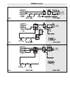
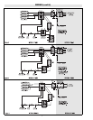
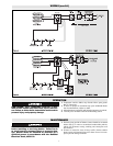
3. Using Wiring Diagram Table B select applicable wiring dia-
gram (Figure 2-9) for proper method of connecting heater.
4. Two or more Type HCH heaters may be controlled by a com-
mon fused disconnect switch providing total branch circuit cur-
rent does not exceed 48 amperes according to National
Electrical Code.
WIRING
ELECTRIC SHOCK HAZARD. Disconnect all power
before installing or servicing heater. Failure to do
so could result in personal injury or property dam-
age. Heater must be installed or serviced by a
qualified person in accordance with the National
Electrical Code, NFPA 70.
1. Locate on vertical wall with length of heater positioned horizon-
tally.
2. When selecting a mounting location, the following minimum dis-
tances must be observed:
A. 6” from bottom of heater to floor to allow for adequate air flow
through the heater.
B. 6” from wall or other obstruction to right side of heater to allow
for access to 1/4 turn fasteners.
C. 12” from wall or other obstruction to left side of heater to allow
for access to controls and wire entry.
3. Avoid mounting heater in a recess since such mounting interferes
with free air circulation, increases heater temperatures, and pre-
vents proper thermostat operation.
4. Remove front cover by giving two fasteners on right end of heater
1/4 turn then sliding cover approximately 1” to right, then lifting.
5. At the correct height for the top of the heater, draw a pencil line on
the wall, parallel to the floor.
6. Using dimensions shown in Figure 1, mark the mounting slot loca-
tion on the wall.
7. Mount heater to the wall by using fasteners (not furnished) to suit
the wall construction. Four 5/16 x 1” mounting slots are provided
in heater back panel. Note: If wall surface is not flat, resulting in
gap between rear case and wall in excess of 1/8” at location of fas-
teners, use metal washers to fill in gap. Tighten left hand fasteners
securely. The right hand fasteners should be pulled up snug to
allow for movement during operation to avoid expansion noise.
8. Replace cover and tighten 1/4 turn fasteners.
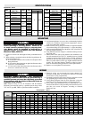
Wiring Diagram Figure No.
208V 240V 480V 550V 575V 600V
120V
277V
3øY 3øY
Model 1ø 1ø 3ø 1ø 3ø 1ø 1ø 3ø (3 Wire) (4 Wire) 3ø 3øY 3ø 3øY 3ø 3øY
HCH-051 2 8 8 2
HCH-071 2 8 8 2
HCH-101 2 8 4 8 4 2 3 9 6
HCH-151 2 8 4 8 4 2 3 9 6 9 9 9
HCH-201 2 8 4 8 4 2 3 9 6 9 9 9
HCH-251 2 8 4 8 4 2 7 5 6 9 9 9
HCH-301 8 4 9 4 2 7 5 6 9 9 9
HCH-351 8 4 8 4 2 7 5 6 5 5 5
HCH-401 8 4 8 4 2 7 5 6 5 5 5
HCH-451 8 4 8 4 2 7 5 6 5 5 5
HCH-501 8 4 8 4 2 7 5 6 5 5 5
Wiring Diagrams — Table B
2
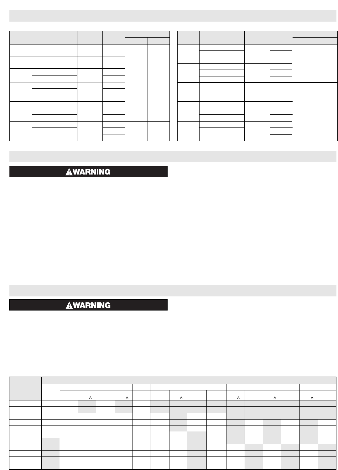
Specifications - Table A
Voltage
Dimensions (In.)
Model
(60 Hz — AC)
Watts Phase
AB
HCH-051
120, 208,
500 1
240 or 277
HCH-071
120, 208,
750 1
240 or 277
HCH-101
120 or 277
1000
1
208, 240 or 480 1 or 3 24 15-7/8
120 or 277 1
HCH-151 208, 240 or 480 1500 1 or 3
550, 575 or 600 3
120 or 277 1
HCH-201 208, 240 or 480 2000 1 or 3
550, 575 or 600 3
120 or 277 1
HCH-251 208, 240 or 480 2500 1 or 3 36 27-7/8
550, 575 or 600 3
Note: Heaters with Model Numbers suffixed with the letter “M” (Ex: HCH-351M) are supplied with a Manual Reset.
Voltage
Dimensions (In.)
Model
(60 Hz — AC)
Watts Phase
AB
277 1
HCH-301 208, 240 or 480 3000 1 or 3
550, 575 or 600 3
36 27-7/8
277 1
HCH-351 208, 240 or 480 3500 1 or 3
550, 575 or 600 3
277 1
HCH-401 208, 240 or 480 4000 1 or 3
550, 575 or 600 3
277 1
HCH-451 208, 240 or 480 4500 1 or 3 48 39-7/8
550, 575 or 600 3
277 1
HCH-501 208, 240 or 480 5000 1 or 3
550, 575 or 600 3