


OPERATION
MAINTENANCE
FIRE HAZARD. Keep combustible materials and
such fabrics at least 4” away from front of cover or
above cover. Failure to comply could result in per-
sonal injury or property damage.
FIRE/EXPLOSION HAZARD. This heater is not
intended for use in hazardous atmospheres where
flammable vapors, gases, liquids or other com-
bustible atmospheres are present as defined in the
National Electrical Code. Failure to comply can
result in personal injury or property damage.
ELECTRIC SHOCK HAZARD. Disconnect all power
before installing or servicing heater. Failure to do
so could result in personal injury or property dam-
age. Heater must be installed by a qualified person
in accordance with the National Electrical Code,
NFPA 70.
1. Following long periods of idleness, heater should be vacuumed
before start-up to remove accumulated combustible particles
which will incinerate causing smoking and consequent wall dis-
coloration.
2. If heater is located in areas of heavy traffic, furnish suitable heater
guard (wall mounted pipe rail in front of case, for example) to pre-
vent damage to heater.
ELECTRIC SHOCK HAZARD. Disconnect all power
before installing or servicing heater. Failure to do
so could result in personal injury or property dam-
age. Heater must be installed by a qualified person
in accordance with the National Electrical Code,
NFPA 70.
ELECTRIC SHOCK HAZARD. Any installation involv-
ing electric heaters must be performed by a quali-
fied person and must be effectively grounded in
accordance with the National Electrical Code to
eliminate shock hazard.
Note: Electrical wiring is to be in accordance with National
Electrical Code.
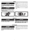
1. Electrical wiring enters heater case through 7/8” opening in back
of heater.
2. Grounding conductor, with green insulation, should be secured
under green colored ground screw located in wiring compartment.
(See Figures 1 and 2).
3. HVT Model only — The white insulated lead of the incoming
power line should be attached to the L1 terminal of the terminal
block. (See Figure 2)
4. Replace cover and end screws (removed in step 4, MOUNTING
section).
WIRING
Figure 1
Figure 2
Heaters
Ground
Heaters
Ground
Thermostat
L1
L2
2