


WIRING
WARNING: Hazard of Electrical Shock. Any installa-
tion involving electric heaters must be effectively
grounded in accordance with the National Electrical
Code to eliminate shock hazard.
1. All wiring should be done in accordance with local codes and the
National Electrical Code by a qualified person.
2. Because of the high operating temperature expected, aluminum
wiring should not be used.
3. When heater element wattages are not equal, heaters must not be
connected electrically in series.
4. Electrical wiring to heater should be contained in rigid conduit or
in sealed flexible hose when corrosive vapors or liquids are pre-
sent. If high humidity is encountered, the conduit should slope
down and away from the heater.
5. If flexible cord is employed, a watertight connector should be
used for entry of the cord into the terminal box. Outdoor applica-
tions require liquid-tight conduit and connectors.
6. Wire separately ordered Hi-Limit and Process Controllers to
thermocouples on heaters.
OPERATION
WARNING: Do not heat materials that are corrosive to
the heating element sheath or chamber.
It is the responsibility of the user to know the chemical composi-
tion of the corrosive solution and the characteristics of the materials
entering the solution as well as the corrosive effect of the solution
upon the heating elements and chamber. Chromalox cannot warrant
any electric circulation heater against failure by sheath corrosion.
1. Do not allow heater to operate when steam, air or gas flow is
interrupted, as dry operation of the heater can cause failure. An
air flow switch should be provided by customer and placed
upstream of the heater inlet.
2. Terminal ends of heater must be protected from drippings,
condensation, spray or direct spill-over of material whose pres-
ence at the terminals may damage heater electrical insulation.
Liquid-resistant terminal enclosures are available to protect
heater. Consult your Local Chromalox Sales office.
3. If foreign material is carried by the gaseous flow, install suitable
filters in the inlet pipe line to the heater.
4. Low Megohm Condition — The refractory material used in elec-
tric heaters may absorb moisture during transit or when subject to
a humid environment. This moisture absorption may result in a
cold insulation resistance of less than twenty megohms.
Normally, this megohm value increases after heatup and does not
affect heater efficiency or life.
A low megohm condition can easily be corrected by removing the
immersion heater from the pipe body, removing the terminal hard-
ware and terminal enclosure and baking the heater in an oven at
350˚-700˚F for several hours, preferably overnight.
Note: The lid from an E2 enclosure may also need removed.
An alternate procedure is to energize the heaters at low voltage
until the megohm reading returns to normal. When energizing
heater without flow, the sheath temperatures should not be
allowed to exceed 750˚F for INCOLOY
®
elements.
MAINTENANCE
1. WARNING: Hazard of Electric Shock. Disconnect
all power before servicing heater.
2. Remove heating element assembly periodically to check heater
sheath for corrosion or excessive oxidation. Correct operating
conditions to minimize sheath deterioration.
3. Periodically check temperature control and pressure-temperature
safety limit control operation to insure accurate and safe process
operation.
4. Check all electrical connections periodically and retighten connec-
tions which may have loosened in service. Replace wire and wire
terminals that show signs of oxidation which would interfere with
establishment of reliable electrical connections.
5. Clean any filters in the inlet pipeline to avoid reduced flow, which
can cause element overheating and premature failure.
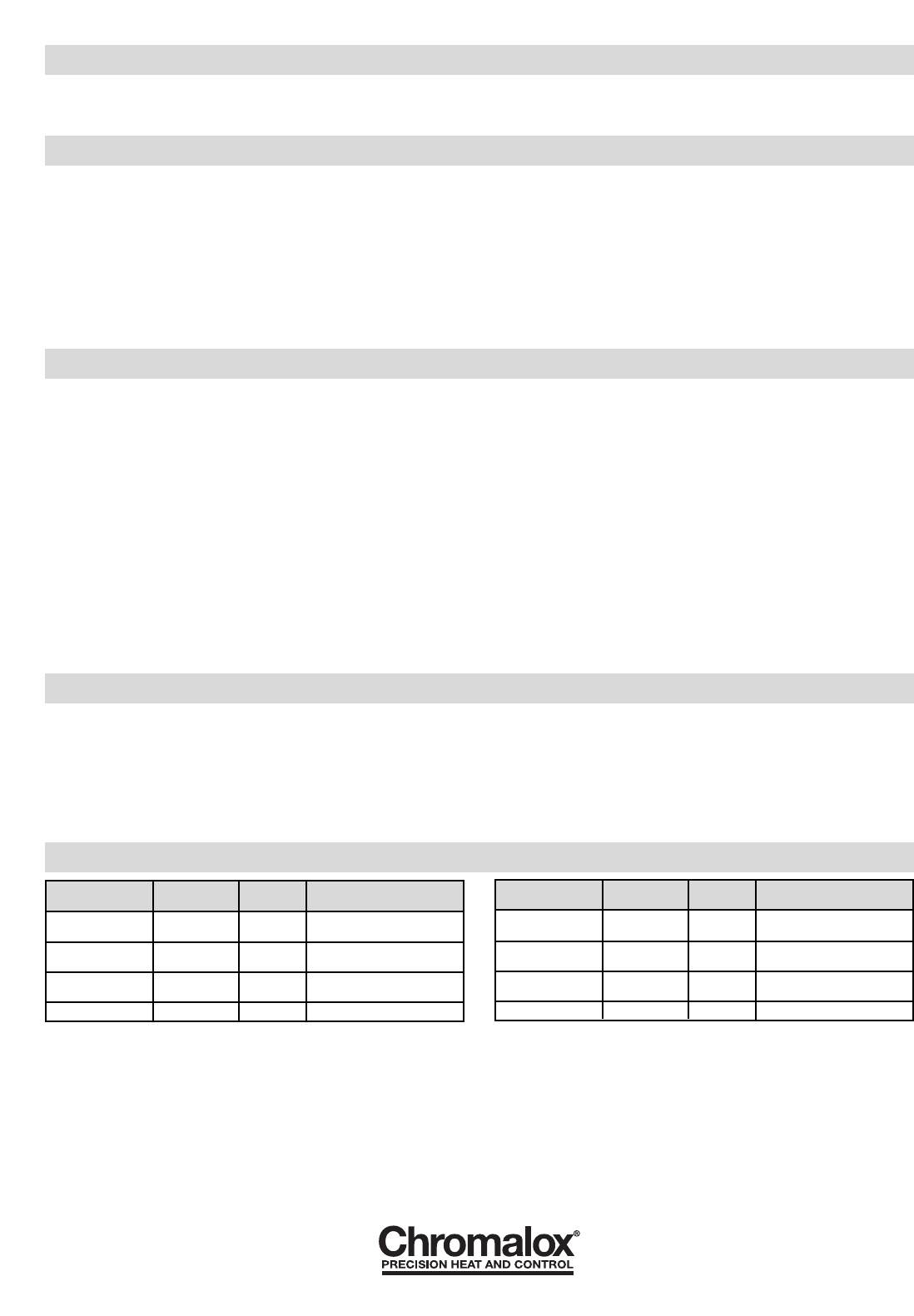
RENEWAL PARTS IDENTIFICATION
2150 N. RULON WHITE BLVD., OGDEN, UT 84404
Phone: 1-800-368-2493 www.chromalox.com
TA - U0 - EF
Litho in U.S.A.
Heater Assembly
Model Volts kW
for E1 Model
GCHIS-C05 120 0.5 042-073644-012
GCHIS-C05 240 0.5 042-073644-040
GCHIS-C10 120 1.0 042-073644-017
GCHIS-C10 240 1.0 042-073644-021
GCHIS-C20 120 2.0 042-073644-028
GCHIS-C20 240 2.0 042-073644-020
GCHIS-C30 240 3.0 042-073644-016
Heater Assembly
Model Volts kW
for E2 Model
GCHIS-C05E2 120 0.5 042-073644-025
GCHIS-C05E2 240 0.5 042-073644-041
GCHIS-C10E2 120 1.0 042-073644-026
GCHIS-C10E2 240 1.0 042-073644-013
GCHIS-C20E2 120 2.0 042-073644-034
GCHIS-C20E2 240 2.0 042-073644-030
GCHIS-C30E2 240 3.0 042-073644-018
Note: When ordering parts for Model Numbers suffixed “XX” or any other letter or letters not specifically identified on this instruction sheet, order Renewal Parts on special order basis, giving name of
part, part number, model number and description.
INSTALLATION
10. DANGER: Possible Explosion. A pressure relief valve
should be provided by customer at outlet of vessel. There should
be no other valving between vessel and relief valve.
11. In a forced circulation system, use pump on the inlet side.
Limited Warranty:
Please refer to the Chromalox limited warranty applicable to this product at
http://www.chromalox.com/customer-service/policies/termsofsale.aspx.