


ELECTRIC SHOCK HAZARD. Disconnect all power
before installing or servicing heater. Failure to do so
could result in personal injury or property damage.
Heater must be installed by a qualified person in accor-
dance with the National Electrical Code, NFPA 70.
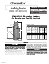
1. Vertical Mounting (Preferred)
When the heater is vertically mounted, the terminal housing will be
at the top of the heater. The inlet pipe will be located on the side
near the bottom of the heater and the outlet pipe at the top.
The axis of the chamber will be in a vertical position as in the
photo on previous page and as in Figure A. Note: A drain pipe
located at the bottom of the heater should be provided and enough
room left, when mounting heater, to allow draining the heater.
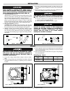
2. Horizontal Mounting (Optional)
CAUTION: When mounting heater horizontally, inlet and outlet
pipes must be up. In any other position, heater cannot be purged of
air, and elements may be seriously damaged. (See Figure B)
3. Whether vertically or horizontally, the heater should be rigidly
mounted so that vibration is at a minimum since excessive vibra-
tion will result in erratic thermostat operation. The NWHO(F)-18
is provided with mounting lugs to support the heating chamber.
(See photo)
4. By using a slotted mounting assembly on either of the lugs, the
heater chamber will be permitted to expand with increasing tem-
perature.
5. Provide adequate space at terminal to end permit withdrawal of the
heater from chamber should servicing be required.
FIRE HAZARD. Since heaters are capable of develop-
ing high temperatures, extreme care should be taken
to:
A. Provide a minimum of 6” spacing from chamber and related
piping to nearest combustible material.
B. Do not operate near combustible fluids or vapors.
FREEZE HAZARD. This unit is equipped with a ther-
mowell for process control or over-temperature
control. Do not allow moisture to accumulate in
thermowell. Freezing temperatures can cause
damage that may result in the heated medium
leaking into terminal enclosure.
240V 3–3Ø 480V 3–3Ø
Model Fig. Fig.
Any Heater 1 2
ELECTRIC SHOCK HAZARD. Any installation involv-
ing electric heaters must be performed by a quali-
fied person and must be effectively grounded in
accordance with the National Electrical Code to
eliminate shock hazard.
1. Be sure line voltage matches heater voltage as shown on name-
plate.
2. Electric wiring to heater must be installed in accordance with local
and National Electrical Codes by a qualified person as defined in
the NEC.
3. Power controllers must be used when heaters are rated for 480 volt
service or if the amperage rating of the heaters exceeds the contact
rating of the thermostat.
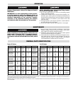
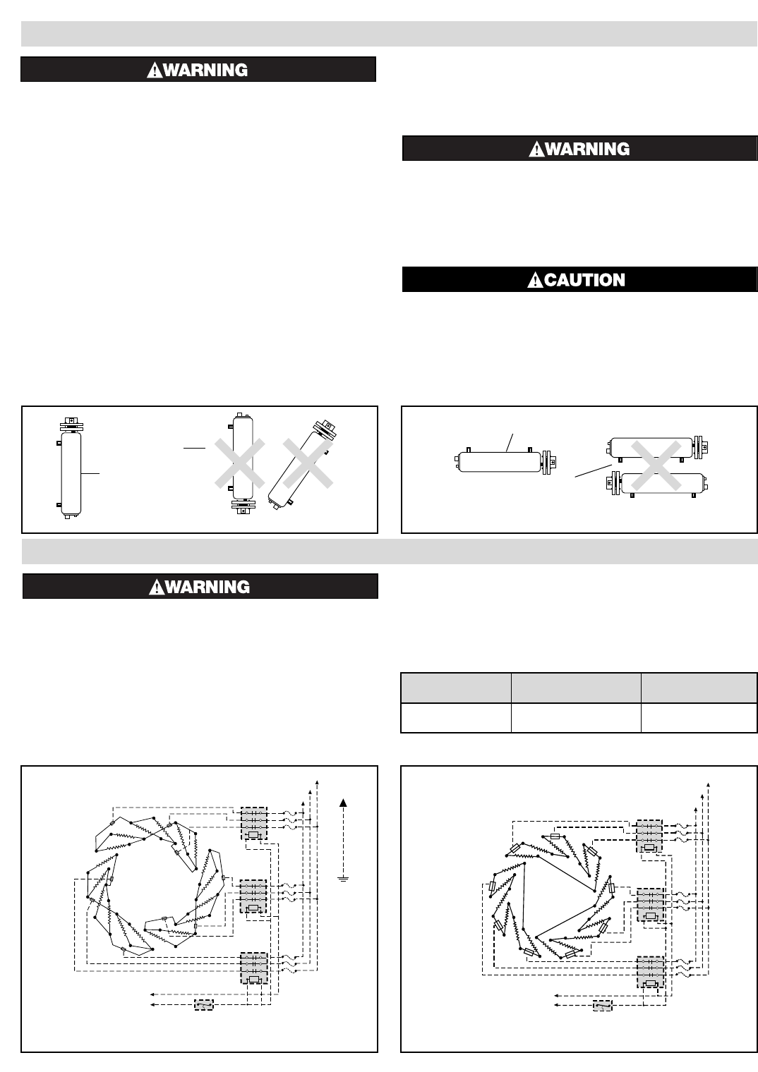
4. Refer to Wiring Diagram Table B for the proper wiring diagram
for connecting heater.
WIRING
Note: Dotted lines indicate “customer furnished.” However, thermostat may be furnished by Chromalox if so specified on the order.
INSTALLATION
Wiring Diagrams – Table B
L1
L2
L3
Contactor
Contactor
Contactor
Thermostat
120-v OR
240-v
Figure 1 – 240V 3-3 ø Δ
120-v OR
240-v
Figure 2 – 480V 3-3 ø Δ
L1
L2
L3
Contactor
Contactor
Contactor
Thermostat
Incorrect
Correct
Figure A — Vertical Mounting
Figure B — Horizontal Mounting
Correct
Incorrect