


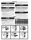
ELECTRIC SHOCK HAZARD. Any installation involv-
ing electric heaters must be performed by a quali-
fied person and must be effectively grounded in
accordance with the National Electrical Code to
eliminate shock hazard.
1. Be sure line voltage matches heater voltage (on nameplate).
2. Electric wiring to heater must be installed in accordance with local
codes and the National Electrical Codes.
3. Because of the high operating temperatures expected, 250˚C wire
should be used.
4. Power controls must be used when heaters are rated 3 phase and
when the heater amperage exceeds the rating of the thermostat.
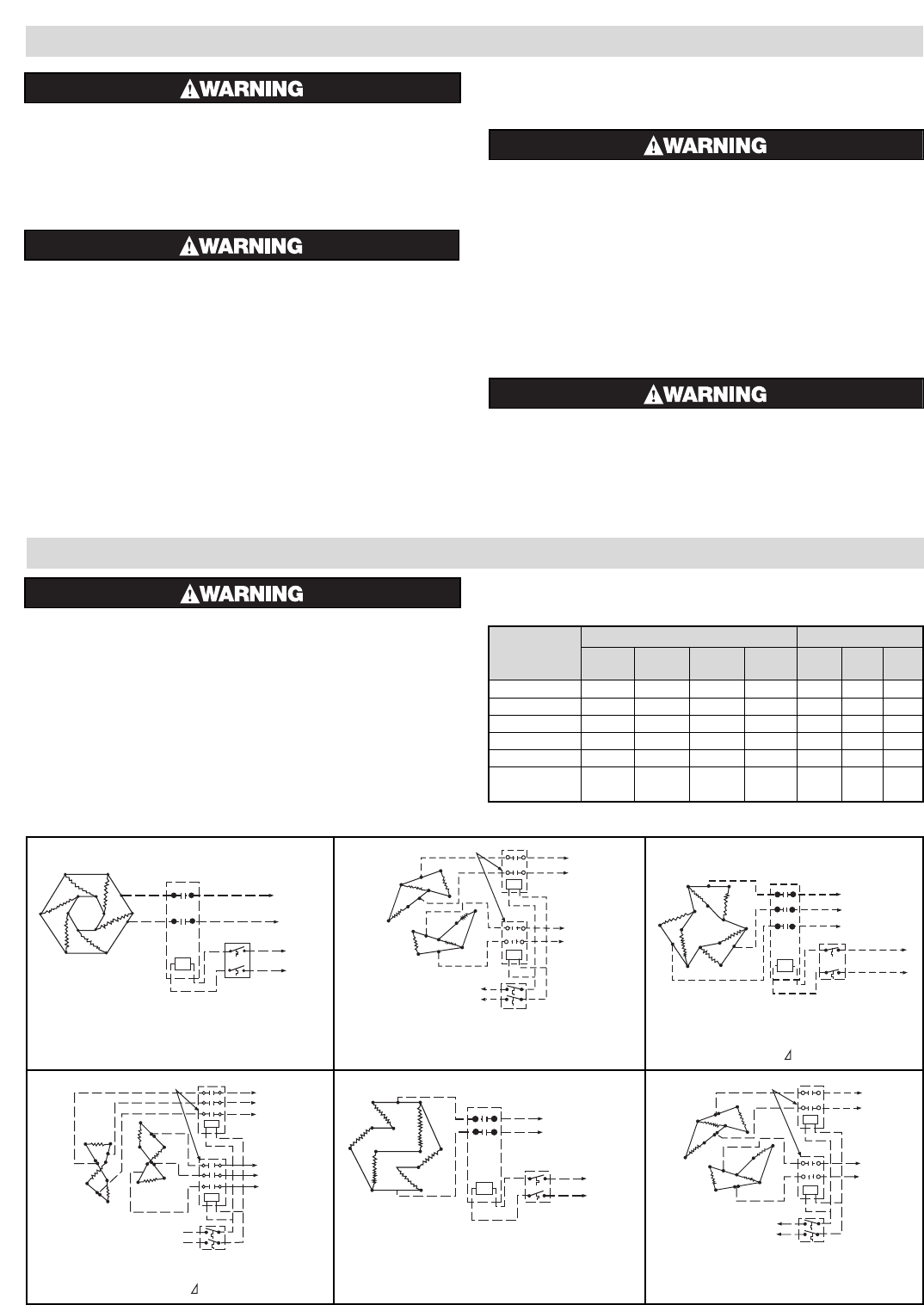
5. Refer to Wiring Diagram Table B, to properly connect the heater.
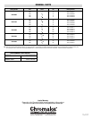
Table B — Wiring Diagrams
WIRING
240V 480V
Model 1ø 2-1ø 3ø 2-3ø 1ø 2-1ø 3ø
Fig. No. Fig. No. Fig. No. Fig. No. Fig. No. Fig. No.Fig. No.
GCH-60905 1 — 3 — 5 — 7
GCH-61205 — 2 3 — 5 — 7
GCH-62005 — 2 — 4 5 — 7
GCH-62505 — — — 4 — 6 7
GCH-63005 — — — 4 — — 7
GCHIS 4, 8
—— 8 ———9
12, 15,20 kW
INSTALLATION
ELECTRIC SHOCK HAZARD. Disconnect all power
before installing or servicing heater. Failure to do
so could result in personal injury or property dam-
age. Heater must be installed by a qualified person
in accordance with the National Electrical Code,
NFPA 70
.
FREEZE HAZARD. This unit is equipped with a ther-
mowell for process control or over-temperature
control. Do not allow moisture to accumulate in
thermowell. Freezing temperatures can cause
damage that may result in the heated medium
leaking into terminal enclosure.
1. Vertical mounting (axis of chamber vertical as in photo on previ-
ous page) is preferred.
2. To avoid excess temperatures at electrical wiring, mount heater
with terminal enclosure at bottom and use lower nozzle as inlet to
the circulating steam, air or gas.
3. The GCH-GCHIS-6 series of circulation heaters are provided with
mounting lugs to support the heater chamber. Refer to photo on
previous page for location of these mounting lugs.
4. Mount heaters to permit unrestrained expansion of chamber due to
temperature. This can be accomplished by using a slotted mount-
ing assembly on either of the lugs.
FIRE HAZARD. Since heaters are capable of devel-
oping high temperatures, extreme care should be
taken to:
A. Provide minimum of 6” spacing from a chamber
and related piping to nearest combustible material.
B. Avoid operation of heater near combustible fluids
or in combustible vapor or gas laden atmosphere.
5. Provide adequate space at terminal end to permit withdrawal of the
heater from chamber should servicing be required.
6. If two or more heaters are needed to provide the needed heating
capacity, arrange them for series gas or vapor flow.
EXPLOSION HAZARD. When heating in closed vessels,
controls and back-up controls must be used to regu-
late build-up of temperature and/or pressure.
7. A pressure relief valve should be provided by customer at outlet
of vessel. There should be no other valving between vessel and
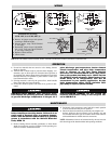
LINE
CONTACTOR
THERMOSTAT
120V, 240V
Figure 1 – GCH6
240V, 1ø
LINE
CONTACTORS
THERMOSTAT
120V or
240V
Figure 2 – GCH6
240V, 2-1ø
CONTACTOR
THERMOSTAT
120V, 240V
Figure 3 – GCH6
240V, 3ø
L1
L2
L3
CONTACTORS
THERMOSTAT
120V
or 240V
Figure 4 – GCH6
240V, 2-3ø
1L1
1L2
1L3
2L1
2L2
2L3
CONTACTORS
THERMOSTAT
120V or 240V
Figure 5 – GCH6
480V, 1ø
LINE
CONTACTORS
THERMOSTAT
120V or
240V
Figure 6 – GCH6
480V, 2-1ø
LINE