


3
WIRING
ELECTRIC SHOCK HAZARD. Any installation involv-
ing electric heaters must be performed by a quali-
fied person and must be effectively grounded in
accordance with the National Electrical Code to
eliminate shock hazard.
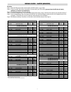
Ensure the correct Wiring Guide is used for your
heated medium and model type, and ensure the
correct wiring diagram is used. Miswiring could
result in an unsafe wattage.
1. Be sure line voltage matches your intended voltage and does
not exceed the max voltage on the nameplate.
2. Electric wiring to heater must be installed in accordance with
local and National Electrical Codes by a qualified person as
defined in the NEC.
3. Power controllers must be used with this product.
4. Electrical wiring to heater should be with rigid conduit or flex-
ible conduit to keep corrosive vapors and liquids out of the
electrical enclosure. If high humidity is encountered, the con-
duit should slope down away from the heater.
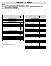
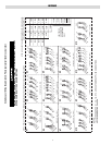
5. Refer to appropriate wiring diagram for your model heater
from the Wiring Guide (on next two pages).
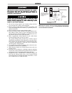
The specific Wiring Guide provides easy to follow steps to
determine the appropriate wiring diagram for your heater instal-
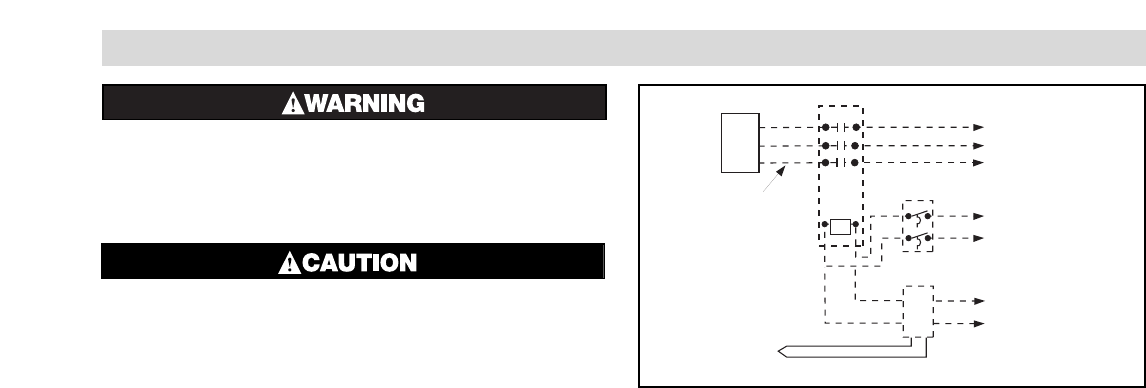
lation. Figure 1 may be referenced as a general diagram of how
a contactor and temperature control are used in conjunction
with the specific wiring diagrams.
6. Use ground fault protection equipment where electrical insula-
tion failure can cause process problems.
7. When element wattages are not equal, heaters must not be con-
nected in series.
8. If flexible cord is employed, a watertight connector should be
used for entry of the cord into the electrical enclosure. Outdoor
applications require liquid-tight conduit and connectors.
9. If application uses a standard PCN at different voltages and
kWs from the Wiring Guide, refer to the Customer Wiring
Guide Supplement if included with these instructions, or con-
tact Customer Service at (800) 368-2493.
Note: Dotted lines indicate “customer furnished.” Complete power/temperature
control panels or components are available. Contact Chromalox 1-800-443-2640
for more information and assistance.
Contactor
Thermostat
L1
L2
To equipment disconnect
with overcurrent protection
L1
L2
L3
Heater
1Ø or 3Ø: Refer to wiring
diagram designated from the
the Wiring Guide for specific
wiring directions to
the heater.
or
Temperature control
L1
L2
Thermocouple
}}
Type "J"
thermocouple
is standard.
Control voltage
Figure 1