


WIRING
WARNING:
Hazard of Electric Shock. Any installation
involving electric heaters must be effectively grounded
in accordance with the National Electrical Code to elim-
inate shock hazard.
1. Electrical wiring to heater must be installed in accordance
with the National Electrical Code and local electric codes by a
qualified person. WARNING: Use copper conductors only.
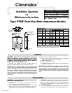
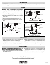
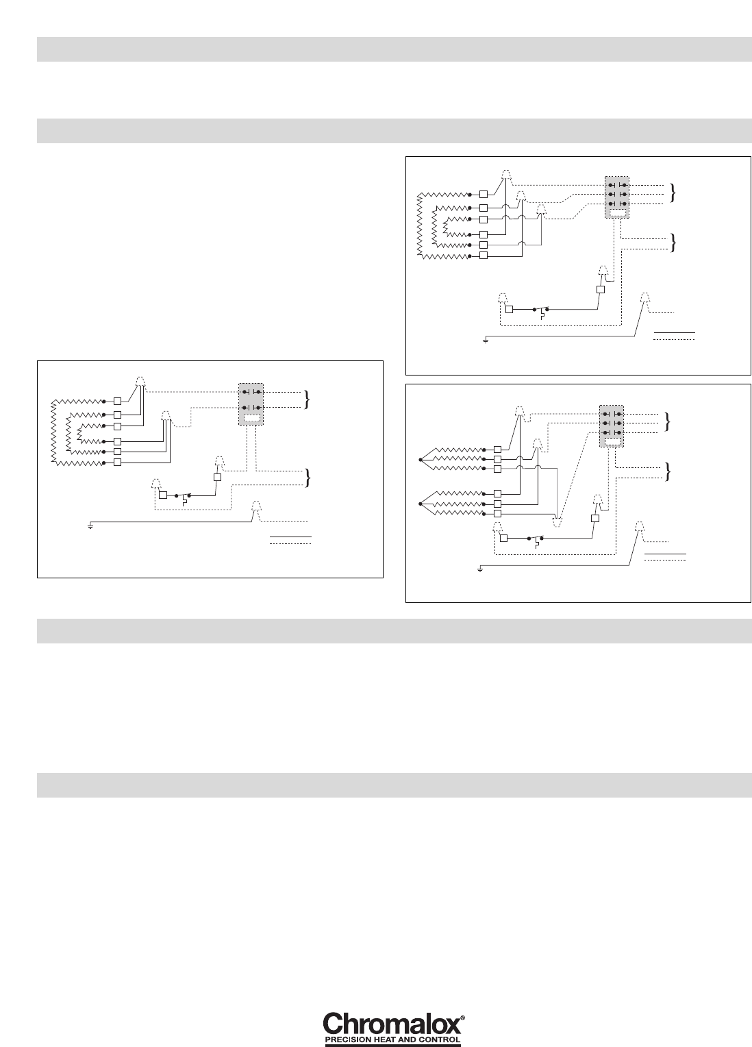
2. Wire heater with manual reset thermal cutout as shown in
Figures 2 thru 4.
Note:
1. Manual reset thermal cutout rating 25 amps 120-277 Vac.
2. Customer supplied thermostat/liquid level control wiring not
shown.
INSTALLATION
5. DANGER: Hazard of Fire. Since these heaters are capa-
ble of developing high temperatures, care should be taken to
maintain liquid level above heated portion (dimension B of
Figure 1) of heater.
OPERATION
1. Do not operate heater at voltages in excess of that stamped on
the heater since excess voltage will shorten heater life.
2. Always maintain a minimum of 2” of solution above the heater
portion of the element to prevent exposure of the effective heated
length. If the heater is not properly submerged, it may overheat
and shorten heater life. Do not operate heater if dry.
(Note: Heated portion of element is Dimension B of Figure 1).
3. Sludge should not be allowed to build-up to the point where it
contacts heater as this can lead to premature heater failure.
4. Maximum recommended process temperature is 212˚F.
5. If manual reset cutout trips, disconnect power to heater and
check for cause of overheat condition. Correct condition, then
remove heater terminal cover and push black reset button to reset
the cutout. Assemble terminal cover before re-energizing heater.
MAINTENANCE
WARNING:
Hazard of Severe Shock. Disconnect all
power to heater before servicing or replacing heaters.
1. Heaters should be checked periodically for corrosion buildup
and cleaned if necessary.
2. Tank should be checked regularly for sediment around the end
of heater as this sediment can act as an insulation and shorten
heater life.
3. WARNING: Do not scratch or scrape thermal cutout capil-
lary when cleaning. Cleaning should be done chemically.
C1
1
2
3
3
2
1
C2
2 Pole Contactor
Customer Supplied
Line Voltage
Ground
Factory
Field
Cutout
Green
120V or 240V
Control Circuit
C1
1
3 Pole Contactor
Customer Supplied
Line Voltage
Ground
Factory
Field
Cutout
Green
120V or 240V
Control Circuit
2
3
3
2
1
C2
C1
3 Pole Contactor
Customer Supplied
Line Voltage
Ground
Factory
Field
Cutout
Green
120V or 240V
Control Circuit
C2
1
2
3
1
2
3
Single Phase for:
PTHF-302, -304, -402, -404
Figure 2
Figure 3
Three Phase for:
PTHF-602, -604, -802, -804, -1002, -1004
Three Phase for:
PTHF-302, -304, -402, -404
Figure 4
2150 N. RULON WHITE BLVD., OGDEN, UT 84404
Phone: 1-800-368-2493 www.chromalox.com
TA - Q0 - EF
Litho in U.S.A.
Limited Warranty:
Please refer to the Chromalox limited warranty applicable to this product at
http://www.chromalox.com/customer-service/policies/termsofsale.aspx.