WIRING
WARNING: Hazard of Shock. Any installation involving
electric heaters must be effectively grounded in
accordance with the National Electrical Code to elim-
inate shock hazard.
1. Electrical wiring to heater must be installed in accordance with the
National Electrical Code and local electrical codes by a qualified
person as defined in the NEC.
2. Because of the high operating temperatures expected, aluminum
wiring is not recommended.
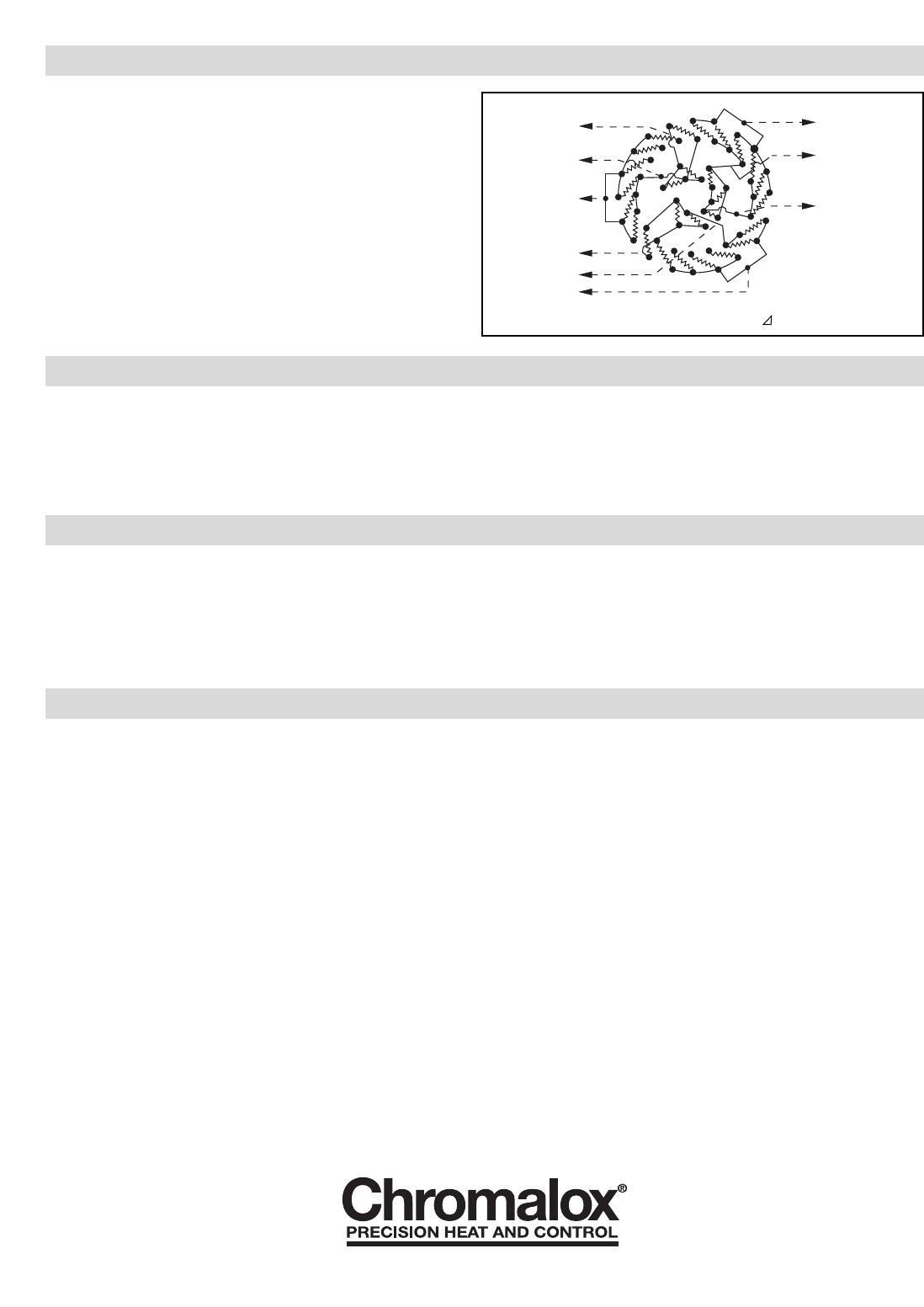
3. Refer to wiring Diagram Figure C for typical wiring used for con-
necting the NWHO-27 series heater.
4. Three 3 phase circuits is a typical design for these heaters. Other
circuit arrangements are often supplied depending upon customer
specifications or amperage rating. Check engineering drawing for
specific wiring diagram of custom orders.
OPERATION
1. Do not heat materials that are corrosive to the heating element
sheath or chamber. For oil heating service, condensate drain may
be provided from bottom of chamber. Check factory.
2. Terminal ends of heater must be protected from drippings conden-
sation, spray or direct spill-over of material whose presence at the
terminals may damage heater’s electrical insulation. Liquid-tight
terminal enclosures are available to protect heater. Check factory.
3. If foreign material is carried by the oil flow, install suitable filters
in the inlet pipe to the heater.
4. Do not allow heater to operate when fluid flow is interrupted.
MAINTENANCE
WARNING: Hazard of Shock. Disconnect all power
before servicing heater.
1. Remove heating element assembly periodically to check heater
sheath for corrosion or excessive oxidation. Correct operating con-
ditions to minimize sheath deterioration.
2. Periodically check temperature control and pressure temperature
safety limit control operation to insure accurate and safe process
operation.
3. Check all electrical connections periodically and retighten connec-
tions which may have loosened in service. Replace wire terminals
which show signs of oxidation which would interfere with estab-
lishment of reliable electrical connections.
RENEWAL PARTS IDENTIFICATION
Order Renewal Parts on a Special Order Basis. Give the name of the part number, voltage, and wattage to your Chromalox Representative for
identification of renewal parts.
2150 N. RULON WHITE BLVD., OGDEN, UT 84404
Phone: 1-800-368-2493 www.chromalox.com
TA - U0 - EF
Litho in U.S.A.
3L1
3L2
3L3
2L1
2L2
2L3
1L1
1L2
1L3
Figure C — 240V, 480V, 3 Phase 3 Circuits
Limited Warranty:
Please refer to the Chromalox limited warranty applicable to this product at
http://www.chromalox.com/customer-service/policies/termsofsale.aspx.


