


OPERATION
1. Do not heat solutions that are corrosive to the heating element
sheath or the heating chamber.
WARNING: Type NWH Circulation Heaters are
equipped with copper heating elements and galva-
nized-steel heating chambers. It is the responsibil-
ity of the user to know the chemical composition
of the corrosive solution and the character of the
materials entering the solution as well as the cor-
rosive effect of the solution upon the heating ele-
ments and chamber. Chromalox cannot warrant
any electric circulation heater against failure by
sheath corrosion if such failure is the result of
operating conditions beyond our control.
2. Terminal ends of heater must be protected from drippings,
condensation, spray or direct spill-over of material. Their
presence at the terminals may damage heater electrical insula-
tion. Liquid-tight terminal enclosures are available to protect
heater. Contact your Local Chromalox Sales office.
3. If foreign material is carried by the liquid flow, install suitable
filters in the inlet pipe line to the heater.
4. Do not allow heater to operate when liquid flow is interrupted.
MAINTENANCE
1. WARNING:
Hazard of Electric Shock. Disconnect all
power before servicing heater.
2. Remove heating element assembly periodically to check
heater sheath for scaling, corrosion or excessive oxidation.
Correct operating conditions to minimize sheath deterioration.
3. Periodically check temperature control and limit control oper-
ation to insure accurate and safe process operation.
4. Check all electrical connections periodically and retighten
connections which may have loosened in service. Replace wire
and wire terminals which show signs of oxidation which would
interfere with establishment of reliable electrical connections.
WIRING
WARNING: Hazard of Electric Shock. Any installation
involving electric heaters must be effectively ground-
ed in accordance with the National Electrical Code to
eliminate shock hazard.
1. Be sure line voltage matches heater voltage (on nameplate).
2. Electric wiring to heater must be installed in accordance with
local and National Electrical Codes.
3. Power controllers must be used when heaters are rated 3 phase and
when the heater amperage exceeds the rating of the thermostat.
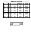
4. Refer to Wiring Diagram, Table B, for the proper wiring diagram
for connecting
heater.
Wiring Diagrams - Table B
INSTALLATION
3. Whether vertically or horizontally, the heater should be rigidly
mounted so that vibration is at a minimum since excessive
vibration will result in erratic thermostat operation. The
NWH-3 is provided with mounting lugs to support the heating
chamber. (See photo.)
4. By using a slotted mounting assembly on either of the lugs,
the heater chamber will be permitted to expand with increas-
ing temperature.
5. DANGER: Hazard of Fire. Provide minimum of 6” spac-
ing from chamber and related piping to nearest combustible
material. Avoid operation of heater near combustible fluids or
in combustible vapor or gas laden atmosphere.
6. Provide adequate space at terminal end to permit withdrawal
of the heater from chamber should servicing be required.
Model
240V, 240V, 480V, 480V,
1 Ø Fig. 3 Ø Δ Fig. 1 Ø Δ Fig. 3 Ø Δ Fig.
NWH-3625 2 1 2 1
NWH-3925 2 1 2 1
NWH-31225 2 1 2 1
NWH-31525 2 1 2 1
NWH-31825 2 1 2 1
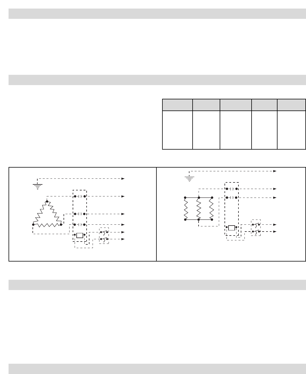
Ground
Contactor
Thermostat
L1
L2
L3
120V
or
240V
Note: Dotted lines indicate “customer furnished.” However, Thermostat could have been furnished by Chromalox if so specified on the order.
Figure 1
240V, 480V 3ØΔ
Figure 2
240V, 480V, 1Ø
Use contactor when the heater amperage
exceeds the rating of the thermostat.
Ground
Contactor
Thermostat
Line
120V
or
240V