


WIRING
OPERATION
MAINTENANCE
RENEWAL PARTS IDENTIFICATION
2150 N. RULON WHITE BLVD., OGDEN, UT 84404
Phone: 1-800-368-2493 www.chromalox.com
TA - O6 - EF
Litho in U.S.A.
WARNING: Hazard of Shock. Any installation involving
electric heaters must be effectively grounded in
accordance with the National Electrical Code to elim-
inate shock hazard.
1. Electrical wiring to heater must be installed in accordance with the
National Electrical Code and local electric codes by a qualified
person as defined in the NEC.
2. When element wattages are not equal, heaters must not be con-
nected in series.
3. Electrical wiring to heater should be contained in Rigid Conduit or
in sealed Flexible Metal hose to keep corrosive vapors and liquid
out of the terminal housing. Conduit should terminate at some
remote area free of corrosive vapors. If high humidity is encoun-
tered, the conduit should slope away from the heater terminals to
keep condensate away from the heater.
4. If flexible cord is employed with the heater, a watertight connec-
tor should be used for entry of the cord into the terminal box.
5. Make sure heater is grounded by attaching ground conductor,
traceable back to service entrance, to the ground terminal located
inside the terminal box. If heater is used in an electroplating tank,
the heater should be grounded externally to the tank wall to mini-
mize stray plating currents in heater sheath that may cause sheath
corrosion.
1. Do not operate heater at voltages in excess of that stamped on the
heater since excess voltage will shorten heater life.
2. Always maintain 6 to 8” of solution above the heated portion of
the element to prevent exposure of the effective heated length. If
the heater is not properly submerged, it may overheat and shorten
heater life.
3. Sludge should not be allowed to build-up to the point where it con-
tacts heater as this can lead to premature heater failure.
4. If heater is inactive for a prolonged period or subjected to exces-
sive moisture during shipments energize at half voltage for a peri-
od of time (generally overnight) before operating at rated voltage.
WARNING: Hazard of Shock. Disconnect all power to
heater before servicing or replacing heaters.
1. Heaters should be checked periodically for coating and corrosion
build-up and cleaned if necessary.
2. Tank should be checked regularly for sediment around the end of
the heater as sediment can act as an insulator and shorten heater
life.
3. Check for loose terminal connections.
4. If corrosion is indicated in the terminal housing, check terminal
box gasket and replace if necessary. Also check the conduit layout
to correct the conditions that allow corrosion to enter the terminal
housing.
Thermostat: (All with 84” capillary)
0-100˚F. . . . . . . . . . . . . . . . . . . . . . . . . . . . . . . . . . 300-048518-005
80-250˚F . . . . . . . . . . . . . . . . . . . . . . . . . . . . . . . . 300-048518-001
200-500˚F . . . . . . . . . . . . . . . . . . . . . . . . . . . . . . . 300-048518-003
Thermostat Mounting Brackets . . . . . . . . . . . . . . . . . 027-072456-001
Thermostat Knob:
0-100˚F . . . . . . . . . . . . . . . . . . . . . . . . . . . . . . . . . . 169-019605-002
60-250˚F . . . . . . . . . . . . . . . . . . . . . . . . . . . . . . . . . 169-019604-001
200-500˚F . . . . . . . . . . . . . . . . . . . . . . . . . . . . . . . . 169-019604-002
Gasket . . . . . . . . . . . . . . . . . . . . . . . . . . . . . . . . . . . . . 132-012603-001
Cover . . . . . . . . . . . . . . . . . . . . . . . . . . . . . . . . . . . . . . 080-012602-001
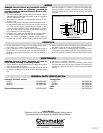
Note: If heater does not exceed the thermostat
capacity (25 amps), a contactor is not needed.
Contactor
120V
or
240V
Thermostat
Junction
Box
Typical Wiring Diagram
L1
L2
Limited Warranty:
Please refer to the Chromalox limited warranty applicable to this product at
http://www.chromalox.com/customer-service/policies/termsofsale.aspx.