


2150 N. RULON WHITE BLVD., OGDEN, UT 84404
Phone: 1-800-368-2493 www.chromalox.com
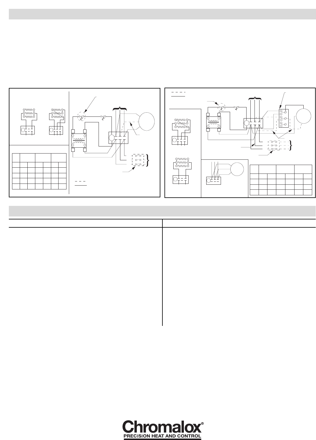
WIRING
The basic stock heater wiring diagram (Figure 4) will be changed
to the finished diagram (Figure 5).
1. Remove the motor lead wires from the heater contactor terminals
marked T1, T2 and T3. (Note that single phase motors will have
only two lead wires.)
2. Connect the black wire (Number 1) from the switch to the T3 ter-
minal on the heater contactor.
3. Connect black wire (Number 3) to contactor terminal marked L3.
4. Connect one of the motor leads to terminal 2 on the switch.
5. Connect the second motor lead to connector terminal marked L1.
ADDITIONAL STEPS FOR HEATERS WITH
THREE (3) PHASE MOTORS
6. Connect black wire (number 9) to contactor terminal marked L2.
7. Connect black wire (number 7) to contactor terminal marked T2.
8. Connect third motor lead wire to terminal 8 on the switch. After
completion of the heater installation, when the fan circuit is first
turned on, check the rotation of the fan to be sure air is moving
from the back of the heater to the front. If the air is moving in the
opposite direction, interchange any two motor lead connections to
correct the air flow direction.
X1
X2
H2H1
C1
Motor
1Ø or 3Ø
L3
L2
L1
T1
T2
T3
3Ø Wiring Only
Power
60Hz
Cutout
XFMR
Optional Thermostat
Built-in or Field Installed
To Element Wiring
3 Phase Delta
C1
T1 T2
T3
L1 L2
L3
C1
T1
T2 T3
L1
L3
1 Phase 2 or 3 Element
Optional Disconnect Switch
Built-in or Field Installed
Built-in or Field Installed
Factory Wiring
Transformer Color Code Index
Pri.
Volt
Pri.
Lead
XFMR
Clrs.
120V
Lead
Sec.
Clrs.
24V
Lead
Sec.
Clrs.
208
240
277
480
H1 H2 X1 X2 X1 X2
WHT
WHT
WHT
WHT
BLK RED
RED RED
RED
RED RED
RED
RED
RED YEL
YEL
YEL
YEL
YEL
YEL
YEL
YEL
YEL
BLU
X1
X2
Motor
1Ø or 3Ø
L3
L2
L1
3Ø Wiring Only
Power
60Hz
Cutout
XFMR
Optional Thermostat
Built-in or Field Installed
To Element Wiring
3 Phase Delta
C1
T1 T2
T3
L1 L2
L3
C1
T1
T2 T3
L1
L3
1 Phase 2 or 3 Element
Optional Disconnect Switch
Built-in or Field Installed
Built-in or Field Installed
Factory Wiring
Transformer Color Code Index
Pri.
Volt
Pri.
Lead
XFMR
Clrs.
120V
Lead
Sec.
Clrs.
24V
Lead
Sec.
Clrs.
208
240
277
H1 H2 X1 X2 X1 X2
WHT
WHT
WHT
BLK RED
RED RED
RED RED
RED
RED YEL
YEL
YEL
YEL
YEL
YEL
YEL
C1
T1 T2 T3
Motor
1Ø or 3Ø
Standard Motor Connection
C1
T1 T2 T3
H1 H2
3Ø Wiring Only
1
3
2
7
9
8
10
12
11
Optional Summer
Fan Switch Built-in
or Field Installed
Figure 4
Figure 5
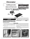
ISFS-02 Kit vs. Applicable Heater Model Number
MODEL
LUH-D-02-81-34-00
LUH-D-02-21-34-00
LUH-D-02-71-35-00
LUH-D-04-81-34-00
LUH-D-04-83-34-00
LUH-D-04-21-34-00
LUH-D-04-23-34-00
LUH-D-04-71-35-00
LUH-D-05-81-34-00
LUH-D-05-83-34-00
LUH-D-05-21-34-00
LUH-D-05-23-34-00
LUH-D-05-71-35-00
LUH-D-07-81-34-00
LUH-D-07-83-34-00
LUH-D-07-21-34-00
LUH-D-07-23-34-00
LUH-D-07-71-35-00
MODEL
LUH-D-10-81-34-00
LUH-D-10-83-34-00
LUH-D-10-21-34-00
LUH-D-10-23-34-00
LUH-D-12-83-34-00
LUH-D-12-23-34-00
LUH-D-15-83-34-00
LUH-D
-15-23-34-00
LUH-D-20-23-34-00
LUH-D-30-83-34-00
LUH-D-30-23-34-00
LUH-D-35-23-34-00
LUH-D-40-23-34-00
MODEL
KUH-C-02-81-00
KUH-C-02-21-00
KUH-C-02-71-00
KUH-C-04-81-00
KUH-C-04-83-34
KUH-C-04-21-00
KUH-C-04-23-34
KUH-C-04-71-00
KUH-C-05-81-00
KUH-C-05-83-34
KUH-C-05-21-00
KUH-C-05-23-34
KUH-C-05-71-00
KUH-C-07-81-34
KUH-C-07-83-34
KUH-C-07-21-34
KUH-C-07-23-34
KUH-C-07-71-30
MODEL
KUH-C-10-81-34
KUH-C-10-83-34
KUH-C-10-21-34
KUH-C-10-23-34
KUH-C-12-83-34
KUH-C-12-23-34
KUH-C-15-83-34
KUH-C-15-23-34
KUH-C-20-23-34
KUH-C-30-83-34
KUH-C-30-23-34
KUH-C-35-23-34
KUH-C-40-23-34
Limited Warranty:
Please refer to the Chromalox limited warranty applicable to this product at
http://www.chromalox.com/customer-service/policies/termsofsale.aspx.