


WARNING: Hazard of Electric Shock. Disconnect all
power before installing heater.
1. Locate on vertical wall with length of heater positioned hori-
zontally.
2. When selecting a mounting location, the following minimum
distances must be observed to insure proper operation.
A. Six (6”) inches from bottom of heater to floor.
B. One (1”) inch from wall or other obstruction to the right or
left side of heater.
3. Do not mount heater in a recess, since such mounting interferes
with free air circulation, increases temperatures and prevents
proper thermostat operation.
4. Mount the rear panel assembly of the heater to the wall using
the
11
/32” dia. holes (bolts to be supplied by customer).
5. Install the perforated cover by hooking the top edge of the
cover over the top edge of rear panel.
6. Attach the bottom lip of the perforated cover to the wall using
the
1
/4-20x1” tamper proof screws.
7. On lower cover assembly connect wires T1-T1 and T2-T2 with
wire nuts provided. Install cover assembly with (2) 10-32x
1
/2
and (1)
1
/4-20x1” tamper proof screws. Use special magnetic
bits provided. (Use standard
5
/16 socket or variable speed drill
when attaching screws.
8. Wire power lines to pigtail leads marked L1 and L2. Connect
ground wire to the green pigtail lead.
9. Adjust thermostat to the desired setting. Install top access
cover with (4) 10-32x
1
/2 tamper proof screws using spanner
tool bits provided.
MOUNTING
WARNING: Hazard of Electrical Shock. Any installa-
tion involving electric heaters must be grounded to
earth to eliminate shock hazard.
Note: Electrical wiring is to be in accordance with National
Electrical Code and local codes using at least 75°C (167°) type
RH, THW or equivalent insulated wire.
1. Electrical wiring must be brought into heater through
13
/32” dia.
hole located in the rear panel.
2. Grounding conductor with green insulation must be connected
to the green pigtail lead.
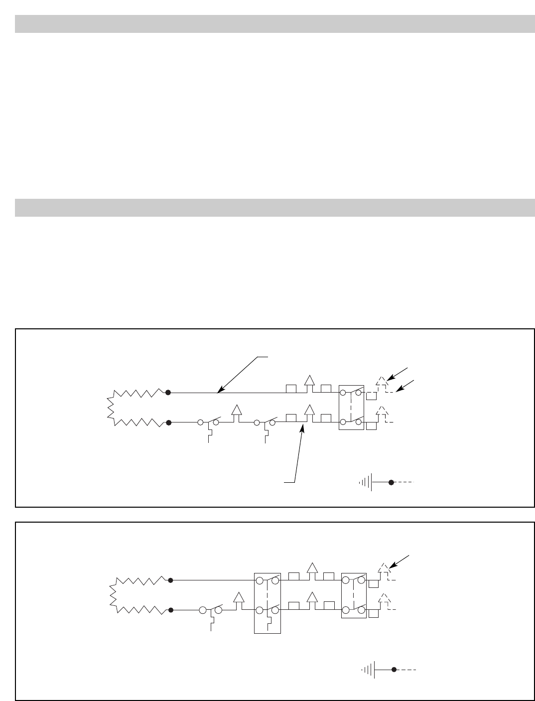
3. Make the proper connections using the appropriate wiring dia-
gram below. Use diagram A for 120 and 277V heaters and use
diagram B for 208 and 240V heaters. These diagrams apply to
all size heaters.
WIRING
White Wire
Heating
Element
Auto
Cutout
T'Stat
Black Wire
Disconnect
Switch
Grd (Green)
Wire Nuts
Common
120 277V
1ø
Power
Circuit
T2
T2
T1
T1
L2
L1
Heating
Element
Auto
Cutout
Double
Pole
T'Stat
Disconnect
Switch
Wire Nuts
208 240V
1ø
Power
Circuit
Grd (Green)
T2
T1
T2
T1
L2
L1
Wiring Diagram A
Wiring Diagram B