


WIRING
ELECTRIC SHOCK HAZARD. Any installation
involving electric heaters must be performed by a
qualified person and must be effectively grounded
in accordance with the National Electrical Code to
eliminate shock hazard.
1. Electrical wiring to heater must be installed in accordance with
the National Electrical Code and local electrical codes by a quali-
fied person.
2. When element wattages are not equal, heaters must not be con-
nected in series.
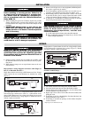
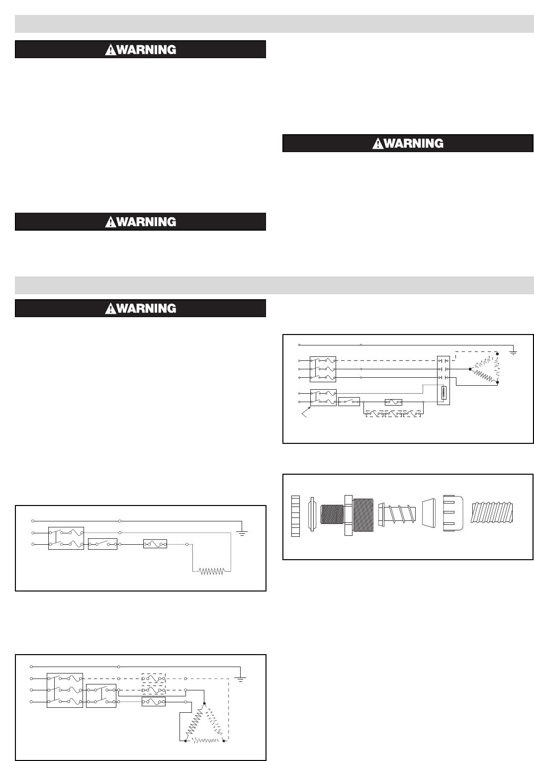
Representative wiring diagrams for heaters with Single use
fuse (F) or Resetable fuse (RF) —
Single phase heater circuit using a SPST thermostat. Line Voltage
and/or current do not exceed thermostat or thermal fuse rating
(Figure 3).
One Single phase heater or (3) single phase heaters equal in size
and each having a thermal fuse wired as a 3 phase heater circuit
using a DPST thermostat. Line voltage and current do not exceed
thermostat or thermal fuse(s) rating (Figure 4). Dotted line and L3
indicate 3 phase connections.
Single phase or 3 phase heater circuit. Line voltage and/or current
exceeds thermostat or thermal fuses ratings (Figure 5). Dotted
line and L3 indicate 3 phase connections.
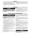
Flexible Conduit Fittings —
1. Cut conduit. Slide nut and sealing insert onto the conduit.
2. Screw the ferrule insert into one end of the flexible conduit.
3. Seat the ferrule insert inside of the body, seat the sealing insert
and hand tighten the cap onto the body.
4. Repeat steps 1 thru 3 above for the other end of the conduit, after
pulling the wires.
5. If the fitting is used in a threaded hole, first thread the body into
the hole then follow steps 1 thru 3.
6. If the fitting is used thru an opening* use the locknut and plastic
washer to fasten it.
* Opening for 1/2” NPT thread is 7/8”.
Ground
L2
Thermostat
Thermal Fuses
Black
Black
Green
Fused
Disconnect
(Customer Supplied)
*
*
*
*
*
*
L3
L1
Heater
Black
Figure 4
Ground
L2
L1
Thermostat
Thermal Fuse
Heater
Black
Black
Green
Fused
Disconnect
(Customer Supplied)
**
Figure 3
Fused Disconnect
(Customer Supplied)
Ground
L3
L2
L1
L2
L1
*
*
Thermostat
Thermal Fuses
Magnetic
Contactor
Black
Black
Heater
Black
Green
Figure 5
Locknut
Washer
Body
Ferrule
Insert
Sealing
Insert
Nut
Conduit
INSTALLATION
ELECTRIC SHOCK HAZARD. Disconnect all power
before installing or servicing heater. Failure to do
so could result in personal injury or property dam-
age. Heater must be installed by a qualified per-
son in accordance with the National Electrical
Code, NFPA 70.
1. Before installing the type GS or GT heater, inspect it for possible
damage which may have occurred during shipment. Also, check
to insure that the line voltage is the same as that stamped on the
nameplate.
2.
IMPORTANT: Mount heater in the tank so the
liquid level will always be above the effective
heated portion of the heater. Provide expansion
tank if necessary.
FIRE HAZARD. If the heater is not properly sub-
merged, the heating elements will overheat and
could result in a fire or damaged equipment..
3. Where work will pass over or near equipment, additional protec-
tion, such as a guard, may be needed.
4. In an electroplating operation the heaters are not, under any cir-
cumstance, to be placed between the electrodes and the work.
5. When melting solids by direct immersion, a surface vent should
be provided to allow gases to escape. Operate the heater on half
voltage until melted material completely covers the heater area.
6. A drip loop is recommended to minimize passage of moisture
along wiring into terminal box and connections.
FIRE HAZARD. Since heaters are capable of devel-
oping high temperatures, extreme care should be
taken to: Since these heaters are capable of
developing high temperatures, extreme care
should be taken to:
A. Avoid contact between heater and combustible material.
B. Keep combustible materials far enough away to be free of the
effects of high temperatures.