


WIRING
ELECTRIC SHOCK HAZARD. Disconnect all power
before installing or servicing thermostat. Failure
to do so could result in personal injury or property
damage. Thermostat must be installed by a quali-
fied person in accordance with the National
Electrical Code, NFPA 70.
ELECTRIC SHOCK HAZARD. Any installation
involving thermostats must be performed by a
qualified person and must be effectively grounded
in accordance with the National Electrical Code to
eliminate shock hazard.
1. Electric wiring to thermostat must be installed in accordance
with the National Electrical Code and with local codes by a quali-
fied person. CAUTION: Use copper conductors only.
2. Entrance for wiring is provided by two 1/2” conduit
holes on each side of the unit.
3. Remove four face mounting screws and pull off front cover.
4. Connect wires according to wiring diagrams (Figures 2 & 3).
5. Replace cover and tighten screws.
6. Note: If load amperage or voltage rating exceeds switch rat-
ing, a contactor must be used. Contactor and wiring to be sup-
plied by customer.
1347 HEIL QUAKER BLVD., LAVERGNE, TN 37086
Phone: (615) 793-3900 www.chromalox.com
MOUNTING
3. NOTICE:
A. Do not bend or deform sensing bulb. This will alter control
calibration.
B. Do not kink capillary tube. The resulting constrictions in
fluid flow can destroy control function or broaden tempera-
ture differential. Minimum capillary tube bending diameter
is 1/2” I.D.
C. Any deformations of bulb or capillary that result in leakage
of fluid from control renders control inoperative.
D. Avoid passing control capillary tube through zones which
have temperatures in excess of controlled process tempera-
ture. Erratic control or destruction of control function may
result.
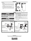
P
NR25
10 AWG
Amber
Neutral
(White)
120V 25 Amps Max Line
Fused Disconnect
By Customer
Hot
(Black)
Ground
(Green)
Nut supplied to
ground control.
Wire Nut
Heater Load
(Black)
Ground
(Green)
CC
NO NO
Connect heater leads
to wire nut provided
and one side of the
terminal block.
Connect heater ground
to ground screw on NR25.
Connect hot line to
screw terminal provided and
neutral line (with pilot light &
heater lead) to wire nut provided.
Connect ground nut on NR25.
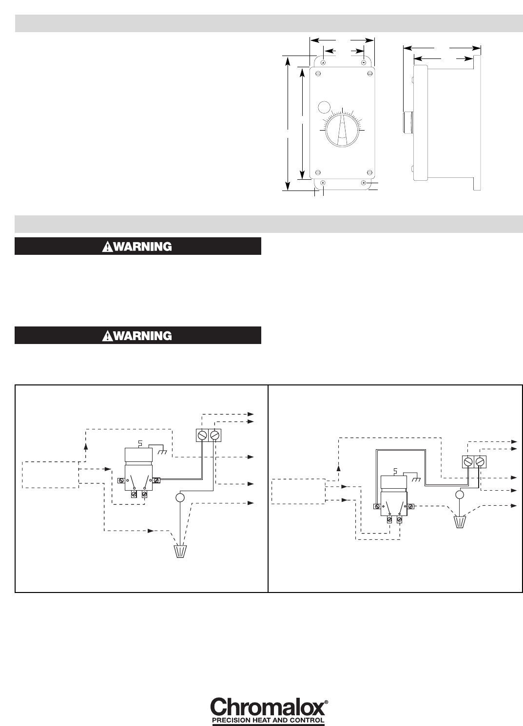
P
NR25
10 AWG
Amber
240V 25 Amps Max Line
Fused Disconnect
By Customer
Ground
(Green)
Nut supplied to
ground control.
Wire Nut
Heater Load
(Black)
Ground
(Green)
CC
NO
NO
Connect wire to 0.250" screw-on
connector. Connect heater lead, pilot light
lead, and wire from control to wire nut
provided. Connect the other heater lead to
the terminal block. Connect heater ground
with grount nut on NR25.
Connect power to 0.250"
screw-on connectors
provided. Connect ground to
ground nut on NR25.
120 Volt 240 Volt
Note: Dotted lines represent wiring by
customer. 10 AWG wire recommended.
Note: Dotted lines represent wiring
by customer. 10 AWG MTW or
THHN wire recommended.
Figure 2
Figure 3
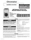
Figure 1
4.25
2.63
5.88
3.75
7.13
0.44
0.44
3.38
Side View
Front View
Note: Terminals provided for ther-
mal fuse or other remote shutdown
device. If no remote device, termi-
nals must be jumpered.
Note: Terminals provided
for thermal fuse or other
remote shutdown device. If
no remote device, termi-
nals must be jumpered.
Limited Warranty:
Please refer to the Chromalox limited warranty applicable to this product at
http://www.chromalox.com/customer-service/policies/termsofsale.aspx.