


INSTALLATION
Figure 4
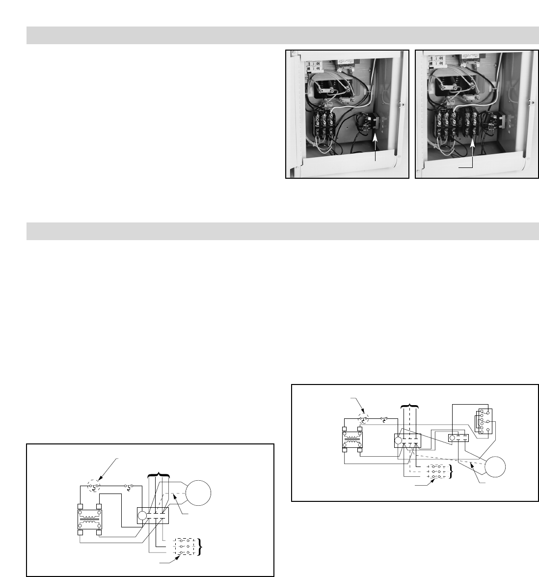
WIRING
The basic stock heater diagram (Figure 6) will be changed to the
finished diagram (Figure 7).
1. Remove the red wire connecting the secondary of the control
transformer to one side of the holding coil on the heater contac-
tor, and discard. Wire the red wire supplied on the fan switch,
(Number 11) to the open connection on the transformer.
2. Connect the black wire (Number 2) on the fan to the relay
coil connection on the fan relay.
3. Connect the remaining black wire (Number 8) to the open
heater contactor coil terminal.
4. Connect the open fan relay coil terminal to the other heater
contactor coil terminal.
HEATERS WITH SINGLE PHASE MOTORS
5. Remove the black and white fan motor lead wires from the
terminals T1 and T3 on the heater contactor and wire them to
the bottom two relay contact terminals. Wire the two loose
jumper wires (supplied) from the top two relay contact termi-
nals to L1 and L3 on the top of the heater contactor.
HEATERS WITH THREE (3) PHASE MOTORS
6. Remove the #1, #2 and #3 motor wires from terminals T1, T2
and T3 on the heater contactor. Connect the #1 wire and #3
wire to the bottom two relay contact terminals. Wire the two
loose jumper wires (supplied) from the top two relay contact
terminals to L1 and L3 on top of the heater contactor. The #2
motor wire should then be connected to terminal T2 on the
heater contactor. After completion of the heater installation,
when the fan circuit is first turned on, check the rotation of the
fan to be sure air is moving from the back of the heater to the
front. If the air is moving in the opposite direction, inter-
change the motor lead connections on the bottom of the relay
which should correct the air flow direction.
X1
X2
Motor
1Ø or 3Ø
L3
L2
L1
Power
60Hz
Cutout
XFMR
To Element Wiring
Optional Disconnect Switch
Built-in or Field Installed
C1
T1 T2 T3
H1 H2
1
3
2
7
9
8
10
12
11
Optional
Thermostat
Built-in or
Field Installed
Use For 3Ø
Figure 7
Figure 5
X1
X2
H2H1
C1
Motor
1Ø or 3Ø
L3
L2
L1
T1
T2
T3
Use For 3Ø
Power
60Hz
Cutout
XFMR
Optional Thermostat
Built-in or Field Installed
To Element Wiring
Optional Disconnect Switch
Built-in or Field Installed
Figure 6
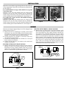
Summer Fan Switch Mounting
Mount the switch with the toggle through the hole from inside the
wiring compartment. Secure the switch using the on/off plate and
hex nut (Figure 4).
For all LUH-2/KUH-2 through LUH-15/KUH-15 except 480
Volt, 3 Phase units
Install the 2 pole relay after checking the coil voltage on the
nameplate to be sure the control voltage of the relay matches the
control voltage of the heater. The relay should be mounted on the
control mounting plate located behind the fan switch (Figure 5).
For all 480 Volt, 3 Phase and all LUH-20/KUH-20 through
LUH-45/KUH-45 units.
Install the 3 pole relay after checking the coil voltage on the
nameplate to be sure the control voltage of the relay matches the
control voltage of the heater. The relay should be mounted on the
control mounting plate located behind the fan switch (Figure 5).
Relay
Mounting