


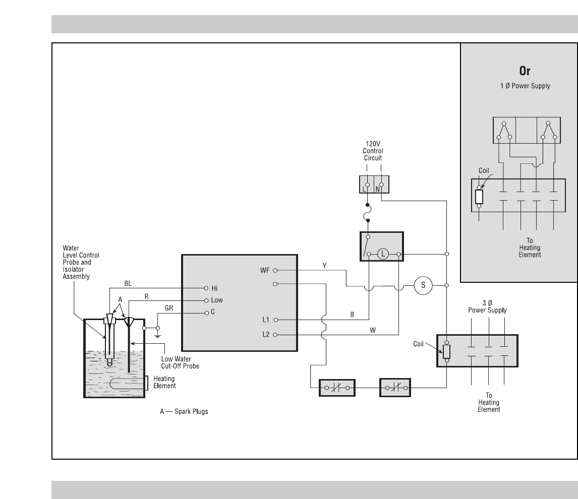
SOLID STATE FLOATLESS LIQUID LEVEL
CONTROL SYSTEM
This boiler is equipped with a solid state, floatless liquid level
control which operates by sensing the electrical resistance of
water. Note: Control will not work with de-ionized or demineral-
ized water. Two probes are provided. The HI probe activates and
controls the feed water relay. The LOW probe is a safety back-up
probe that turns off the power to the element in the event of low
water. A 12 volt potential is established between each probe and
ground. The presence or absence of water generates a small signal
that is amplified and fed to a SCR. The SCR, in turn, activates a
relay, depending on the function and the water level.
ADJUSTING PRESSURE CONTROLS
Chromalox boilers are supplied with operating and high limit pres-
sure controls. One is used for controlling the operating pressure of
the boiler while the other is used as a high limit control.
MANUAL BLOWDOWN INSTRUCTIONS
Blowdown is an essential part of boiler operation. It is the best
preventive maintenance you can give your boiler and will add
years of life to the unit. Make sure a blowdown schedule is estab-
lished and followed regularly.
Blowdown will remove accumulated hard water scale and dis-
lodge scale from water heating surface thereby insuring efficient
heating. In extremely hard water areas blowdown is necessary
once a day. In soft water areas, once each week. If water is known
to be corrosive, consult water treating specialists to recommend
water treatment needed to insure corrosion free boiler operation. If
there is a particular problem which applies to your own local water
condition other than mineral content, take this into consideration
in determining what schedule is to be followed.
1. At the end of the working day turn switch to the OFF position
and close water supply valve. De-energize wall mounted safe-
ty switch (main power supply).
2. If blowing down into a receptacle, cover receptacle to prevent
splash of scalding water.
3. It is preferable to connect the blowdown valve directly into a
drainage system. If this is done, the boiler can be discharged at
operating pressure. However, check local codes and suitability
of drainage system before connecting.
4. When blowdown is complete and boiler is drained (a) close the
blowdown valve; (b) open water supply valve; (c) put boiler
switch in the ON position; and, (d) close wall mounted safety
switch.
5. When refilling is complete, turn off the boiler switch unless
further operation is desired.
The use of chemical boiler cleaning compounds in these boilers
voids all warranties unless approved by Chromalox, Inc.
-3-
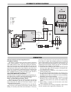
SCHEMATIC WIRING DIAGRAM
OPERATION
HTR
O
Wire Color Code —
B = Black
W = White
R = Red
O = Orange
Y = Yellow
GR = Green
BL = Blue