


2150 N. RULON WHITE BLVD., OGDEN, UT 84404
Phone: 1-800-368-2493 www.chromalox.com
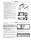
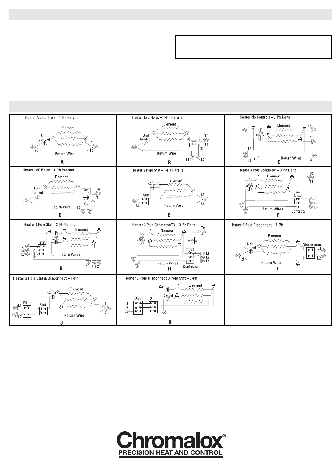
1. Wire all heaters and controls in accordance with the appropri-
ate wiring diagram provided below.
2. Run a ground jumper from the ground screw in one terminal
box to the ground screw in the adjacent terminal box. (See
Figure 4.)
3. Do a final and complete check of all wiring then replace the
terminal box covers being careful not to pinch any wires.
4. The front panel may now be installed.
5. Place the front panel over the flange of the bottom panel.
Hook the top back edge of the front panel over the top panel,
and secure with screws.
Table 2: Terminal Box Volumes (Cubic Inches)
WARNING: TO PREVENT THE RISK OF FIRE, DO NOT
OPERATE THE HEATER WITHOUT THE FRONT
PANEL IN PLACE.
Heater Style Left Hand Box Right Hand Box
4” Wide 5” Wide
CAF-12, CCAS-12 146.25 182.75
WIRING
WIRING DIAGRAMS
Limited Warranty:
Please refer to the Chromalox limited warranty applicable to this product at
http://www.chromalox.com/customer-service/policies/termsofsale.aspx.