


WIRING
WARNING: Hazard of Electric Shock. Any installation
involving electric heaters must be effectively ground-
ed in accordance with the National Electrical Code to
eliminate shock hazard.
1. All wiring should be done in accordance with the National
Electrical Code and with local codes by a qualified person.
2. Connect air heaters to same line voltage, phase and frequency
as on heater nameplate.
3. Teflon insulated nickel plated copper wire or buss bar is rec-
ommended for power connections to heater terminals and for
wiring runs in heated zones. When ambient temperature in
heated zone exceeds that for which insulated wire is recom-
mended use bare nickel-plated copper with porcelain beads,
tubing or buss bar. Consult local Chromalox representative.
4. Users should install adequate back-up controls and safety
devices with their electric heating equipment. Selection of
controls, thermostat, SCR units, contactors and etc. depends
on the degree of accuracy required, reliability, electrical rating
of heater and economic considerations.
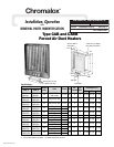
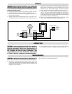
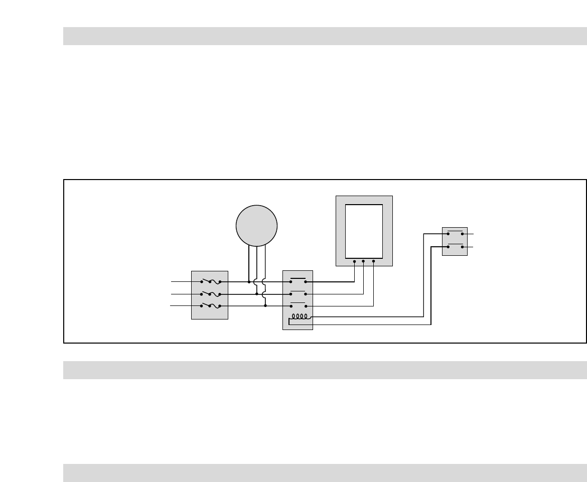
5. Below is an example of standard CAB 122 480V 3P 12 kW
wired with recommended back-up controls (Figure 3).
OPERATION
WARNING: Users should install adequate back-up
controls and safety devices with their electric
heating equipment. Where the consequences of
failure may be severe, back-up controls are essen-
tial. Although the safety of the installation is the
responsibility of the user, Chromalox will be glad
to assist in making equipment recommendations.
1. Do not operate heaters at voltages in excess of that stamped
on the heater since excess voltage will shorten heater life.
MAINTENANCE
WARNING: Hazard of Severe Shock. Disconnect all
power to heater before servicing or replacing heaters.
1. Periodically clean terminals and terminal covers of dust and
corrosion to maintain good electrical connections and to per-
mit rapid heat dissipation. Use airblast, and be careful to avoid
damage to mica insulation.
2. Check for loose terminal connections.
Fused Switch
480V
Power
Supply
Heater
Contactor
Thermal Cutout
Fan
Motor
120/240
Control
Circuit
Figure 3 - Wiring Diagram