


Installation Instructions Model: TPS-2000 SERIES
3
INSTALLATION
Pole Mount
WARNING: THE STRUCTURAL MEMBER MUST BE
CAPABLE OF SUPPORTING 4 TIMES THE
COMBINED WEIGHT OF ALL COMPONENTS PLUS
THE EQUIPMENT BEING MOUNTED.
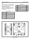
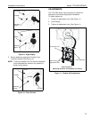
1. Verify truss plate (10) is properly oriented for
installation.
Figure 2: Truss Plate Orientation for Pole Installation
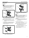
2. Attach truss plate (10) to pole using Chief accessory
clamps or equivalent. (See Figure 3)
NOTE: Contact Chief Customer Service at 1-800-582-
6480 to identify the proper mounting clamp for the
installation.
3. Adjust truss plate (10) vertical and horizontal position
until desired location is obtained. (See Figure 4)
4. Secure truss plate to pole by tightening clamp
hardware. (See Figure 4)
Figure 3: Install Back Plate to Pole
Figure 4: Position and Secure Back Plate
Truss Mount
WARNING: THE STRUCTURAL MEMBER MUST BE
CAPABLE OF SUPPORTING 4 TIMES THE
COMBINED WEIGHT OF ALL COMPONENTS PLUS
THE EQUIPMENT BEING MOUNTED.
1. Verify truss plate (10) is properly oriented for
installation.
NOTE: The orientation of the truss plate when mounted
on a truss is the same as when mounted on a
pole. (See Figure 2)
2. Locate mount location on truss.
3. Attach truss plate (10) to truss using Chief accessory
clamps or equivalent. (See Figure 3)
NOTE: Refer to page 2 of this document for available
Chief mounting clamp kits. See Available
Mounting Clamp Kits on page -2
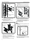
4. Adjust truss plate (10) vertical position until desired
location is obtained. (See Figure 4)
5. Secure truss plate to truss by tightening clamp
hardware. (see Figure 5)
Slot at bottom
Recessed, Slotted Flat Surface
Against Pole
10
10
Clamp
10
Tighten Clamp Hardware
(4 places)