


Instruction Manual TPP
5
Mount the Display
1. Attach included PSB brackets to your display using the instruc-
tions included with the PSB package.
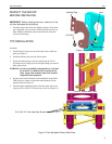
2. Make sure no power is supplied to the display and the flag is in
the down position before attempting to mount the display.
3. Using two people, slide the display down over the four slots in
the face plate of the TPP. Make sure all four Quick Latches (Q-
Latches) of the display engage all four slots in the TPP.
WARNING: Make sure the flag securing the display is com-
pletely raised at all times except when removing or
installing the display. The flag must be all the way
up when installing/removing cables.
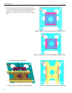
4. With the Q-Latches of the display fully engaged in the slots of
the TPP, secure the display on the TPP by raising the flag all
the way up to the locked position (see Figure 8). If the flag
does not fully engage, remove the display and make sure the
brackets are correctly installed.
NOTE: A security lock may be installed through the hole in the
flag for additional security.
Tilt Adjustment
WARNING: Watch for pinch points. Do not put your fingers
between movable parts.
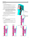
1. Loosen tilt adjustment screws, adjust to desired tilt, and tighten
tilt adjustment screws if necessary (see Figure 9).
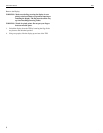
2. Loosen tilt adjustment screws, adjust to desired tilt, and tighten
tilt adjustment screws if necessary (see Figure 10, Figure 11,
and Figure 12).
Q-Latch Engaged
Figure 8. Engage Q-Latch
Tilt Adjustment Screw
(One Each Side)
Figure 9. Tilt Adjustment Screw Location
Figure 10. 0 Degree Tilt
0 Degree
(Outside Hole)
Figure 11. 5 Degree Tilt
(Tilt Hole)
10 Degree
(Tilt Hole)
Figure 12. 10 Degree Tilt
5 Degree