


MF1, MF2, PF1, PF2 Series Installation Instructions
8
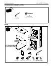
Attaching Display to Stand
WARNING: EXCEEDING MAXIMUM WEIGHT CAPACITY
MAY LEAD TO SERIOUS PERSONAL INJURY OR
DAMAGE TO EQUIPMENT! It is the installer’s responsibility
to ensure the total amount of weight placed on the stand
does not exceed 125 lbs (56.70 kg) for the MF1, 250 lbs
(113.40 kg) for the MF2 [125 lbs (56.70 kg) per faceplate];
200 lbs (90.72 kg) for the PF1, 400 lbs (181.44 kg) for the
PF2 [200 lbs (90.72 kg) per faceplate].
CAUTION: Before attaching display(s) to the stand ensure
the stand is on level surface.
CAUTION: ALWAYS remove the display(s) BEFORE
adjusting the height of the stand.
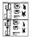
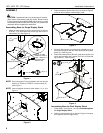
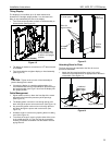
1. Adjust the stand to the desired height by holding the top part
of the post, pulling out knob on the center post and turning
90
o
in either direction to disengage the locking mechanism.
(See Figure 9)
Figure 9
2. Raise or lower the center post, then turn the knob 90
o
either
direction to engage the knob and lock the stand at desired
height. (See Figure 9)
IMPORTANT ! : Set the height of the stand so the display
does NOT rest on the lower part of the post. (See
Figure 9) Always set the height so the knob is engaged in
a hole in the center post.
3. Attach PSBU or MSBU interface bracket(s) to the display(s)
following the instructions included with the bracket.
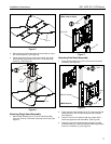
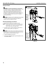
4. While supporting both sides of display, align four mounting
buttons on display or interface bracket with four mounting
holes in head assembly. (See Figures 10 and 11)
Figure 10
WARNING: EACH DISPLAY MAY WEIGH IN EXCESS OF
40 LBS! Always use two people and proper lifting techniques
when installing or positioning display on stand.
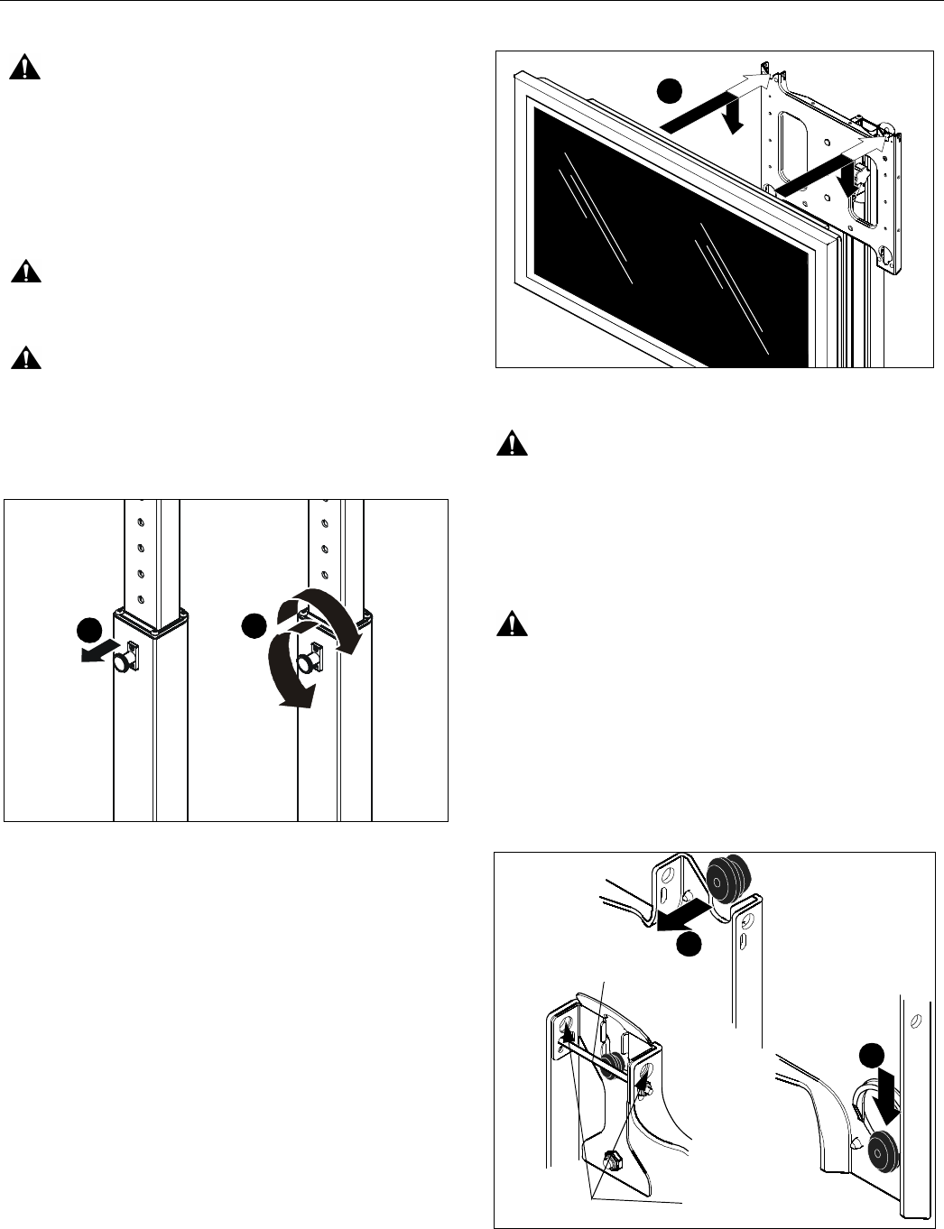
5. Lower display into place listening for audible "click" to
ensure recessed area of mounting buttons are properly
seated in lower area of mounting holes.
(See Figures 10 and 11)
WARNING: IMPROPER INSTALLATION CAN LEAD TO
STAND OR DISPLAY FALLING CAUSING SERIOUS
PERSONAL INJURY OR DAMAGE TO EQUIPMENT!
Ensure mounting buttons are completely engaged in
mounting holes.
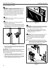
NOTE: Holes are provided in the faceplate for use with a
padlock or similar locking device, if desired. In addition,
the pin and nut may be removed from the upper holes
and moved to the lower holes for use as a more
permanent locking device. (See Figure 11)
Figure 11
1
2
5
5
4
Remove pin
and nut and
move to lower holes
A padlock or bolt may
be placed through latch
holes