


J-Series Installation Instructions
6
INSTALLATION
WARNING: FAILURE TO PROVIDE ADEQUATE
STRUCTURAL STRENGTH FOR THIS MOUNT CAN
RESULT IN SERIOUS PERSONAL INJURY OR DAMAGE
TO EQUIPMENT! It is the installer’s responsibility to make
sure the structure to which this mount is attached can support
five times the combined weight of the mount and all
equipment attached to it. Reinforce the structure as required
before installing the mount.
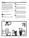
1. Determine location for mount keeping in mind display size,
extension, height adjustment (if applicable), and pitch/roll
requirements.
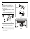
NOTE: Wall plate (D) MUST be installed into wood stud.
2. Using wall plate (D) as a template, mark then drill two 1/8"
diameter pilot holes through top and bottom holes of wall
bracket into wall structure. (See Figure 1)
Figure 1
3. Install two 3/8" x 3" hex head lag screws (F) through wall
plate (D) and drywall into wood stud. (See Figure 1)
4. Ensure wall plate (D) is vertical, then tighten screws (D).
CAUTION: Overtightening screws may cause wall bracket
to compress into soft wall surface, resulting in difficult mount
installation or improper engaging of set screw in later step.
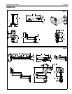
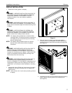
5. Insert top of wall mount (A, B or C) over lip on top of wall
plate (D). (See Figure 2)
6. Swing wall mount down flush against wall.
Figure 2
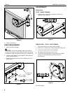
7. Tighten set screw in bottom of wall mount. (See Figure 3)
NOTE: Ensure set screw engages on back side of wall plate to
properly secure wall mount.
Figure 3
2
3
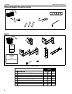
(F) x 2
(A, B or C)
(D)
5
6
(A, B or C)
(D)
7
Set
Screw