


JHS SERIES Installation Instructions
4
INSTALLATION
Mount Installation
IMPORTANT ! : The following installation instructions
assume that a 1-1/2" NPT pipe has been properly
installed and is in place.
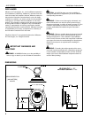
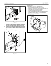
1. Thread mount (A) onto 1-1/2" NPT pipe until hand tight.
2. Adjust mount (A) position until Centris cup is facing the
desired position of the display. (See Figure 1)
Figure 1
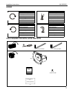
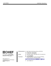
3. When mount (A) is properly positioned secure mount (A) to
1-1/2" NPT pipe by installing and tightening 5/16-18 x 3/8"
set screw (B) using 3/16" hex wrench. (See Figure 2)
NOTE: If mount is being used to couple two pipes, use both set
screws when securing mount (A) to pipes.
Figure 2
Display Installation
1. Determine mounting pattern on display.
WARNING: IMPROPER INSTALLATION CAN LEAD TO
EQUIPMENT FALLING CAUSING SERIOUS PERSONAL
INJURY AND DAMAGE TO EQUIPMENT! DO NOT
substitute hardware. Use only hardware supplied by
manufacturer!
WARNING: IMPROPER INSTALLATION CAN LEAD TO
ELECTRIC SHOCK OR DAMAGE TO EQUIPMENT! Screw
length must not exceed the depth of threaded mounting insert
in display.
WARNING: OVERTIGHTENING OF SCREWS CAN
DAMAGE PARTS AND LEAD TO SERIOUS PERSONAL
INJURY AND DAMAGE TO EQUIPMENT! DO NOT over
tighten screws when installing interface bracket.
NOTE: If the display being installed has a 100x100 VESA
mounting pattern, no interface bracket is required and
the display can be mounted directly to the Centris cup
as outlined below.
NOTE: If the display being installed requires an interface
bracket, refer to the interface bracket installation
instructions.
WARNING: IMPROPER INSTALLATION CAN LEAD TO
DISPLAY FALLING CAUSING SERIOUS PERSONAL
INJURY OR DAMAGE TO EQUIPMENT! Using screws of
improper size may damage your display! Proper screws will
easily and completely thread into display mounting holes.
Ensure that screws are not too long.
WARNING: IMPROPER INSTALLATION CAN LEAD TO
DISPLAY FALLING CAUSING SERIOUS PERSONAL
INJURY OR DAMAGE TO EQUIPMENT! Inadequate thread
engagement in display may cause display to fall! Back out
screws ONLY as necessary to allow installation of Centris
cup!
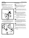
1. Start two M4 x 8mm Phillips pan head screws (included in
hardware kit) into upper mounting holes in display back.
(See Figure 3)
NOTE: Leave at least 1/8" of each screw protruding out back
of display.
1
1-1/2" NPT Pipe
Centris Cup
(A)
2
(B) x 1
(A)
2
(A)
(B) x 1