


Installation Instructions FSD-4100
5
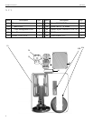
FSD-4100 INSTALLATION
WARNING: It is the responsibility of the installer to verify that
the surface to which the FSD-4100 is anchored will
safety support the combined load of all attached
components and equipment.
Install the FSD-4100 as follows:
NOTE: Numbers in ( ) refer to parts in PARTS on page 4.
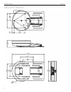
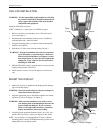
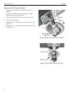
1. Remove two screws securing base cover (10A) and remove
cover (see Figure 1).
2. Determine the exact mounting location prior to installation,
considering the unit’s total arm radius.
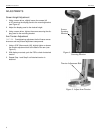
3. Using the mounting plate as a template, mark mounting hole
locations (see Figure 2).
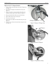
4. Drill three 1/4” holes at the locations marked in step 3.
WARNING: Improper installation can result in serious dam-
age to the display or personal injury! Make sure
that the structural members can support a redun-
dant weight factor five times the total weight of the
equipment. If not, reinforce the structure before
installing the FSD-4100.
5. With the FSD-4100 correctly oriented and level, secure it to the
surface using fasteners (20 and 30).
6. Check mount to insure it is level and adjust to level if neces-
sary.
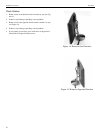
MOUNT THE DISPLAY
1. Make sure no power is supplied to the display before attempt-
ing to mount the display.
WARNING: Watch for pinch points. Do not put your fingers or
cables between movable parts.
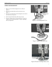
2. Align the appropriate slots in the bracket with the four mount-
ing holes of your LCD display (see Figure 3).
WARNING: Make sure the mounting screws used to secure
your display panel to the mounting bracket are the
proper length and diameter. If you are unsure
about screw length and/or diameter, consult the
display manufacturer before proceeding.
3. Using the proper length and diameter screws (40 or 50), and
spacers (60) as necessary, secure your display to the mount.
NOTE: If your display is not equippedwith 75 \mm or 100mm
mounting pattern, contact Chief Manufacturing to check for an
adapter plate for your display model.
Base
Screws
Cover
Secure
Display
Figure 1. Remove Cover
Figure 3. Secure Display
Figure 2. Mark Mounting Location
Mark
Hole
Locations