


Installation Instructions FHP
5
DISPLAY INSTALLATION
Install the display as follows:
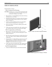
VESA Compliant Flush Mounting
CAUTION: If monitor uses a screw size other than M4, DO NOT
use the M4 screws provided. Using the wrong screws
could result in damage to your display.
1. Start two M4 X .7 X 12mm Phillips pan head screws in the top
mounting holes of your display.
2. Matching the hole pattern on your display with the hole pattern
on the mount, hang the mount from the two screws started in
Step A (see Figure 3).
3. Install two remaining Phillips pan head screws through the
mount and into the mounting holes of your display.
4. Secure your display to the mount by tightening the four Phil-
lips pan head screws.
5. Connect and secure power/audio/video cables, making sure to
leave sufficient slack to allow for movement of the display.
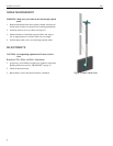
VESA Compliant Recessed Mounting
1. Place four 1/2” X 3/8” Nylon spacers or four 1/2” X 3/4”
Nylon spacers, as necessary, over the mounting holes of your
display (see Figure 4).
2. Place the mount over the Nylon spacers, matching the hole pat-
tern on your display (75mm or 100mm) with the hole pattern
on the mount.
3. Using four M4 X .7 X 20mm Phillips pan head screws for 1/2”
X 3/8” Nylon spacer installation or four M4 X .7 X 30mm
Phillips pan head screws for the 1/2” X 3/4” Nylon spacer
installation, secure the mount to your display.
4. Connect and secure power/audio/video cables, making sure to
leave sufficient slack to allow for movement of the display.
Non-VESA Compliant Mounts
1. Contact Chief Manufacturing for custom interface brackets.
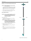
Figure 3. Install Flush Mount Display on Bracket
Figure 4. Install Recessed Mount Display on Bracket