


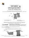

8803-000033 01/26/04
CHIEF MANUFACTURING INC. 1-800-582-6480, Fax: 1-877-894-6918, Email: chief@chiefmfg.com
Pole-Mounting Bracket Assembly and Installation:
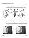
1. Assemble two pole-mounting bracket halves as shown in Figure 3 and secure using two ¼-20 X 4.25”
hex bolts and two ¼” flat washers.
2. For vertical pole mounting, install the pole-mounting bracket on 1 ½” to 2” OD pipe/pole and secure
using 7/16” hex drives (see Figure 4).
3. For horizontal pole mounting; remove eight tilt adjustment screws, reposition the tilt bracket as
shown in Figure 5, and insert nylon spacers. Secure using 10-24 x 1.00 screws provided.
Mounting Display with Interface Bracket to Pole-Mounting Bracket:
1. Make sure both latching flags on pole-mounting bracket are in the unlocked position (see Figure 4).
2. Place your small flat panel displays; with interface brackets attached, onto the pole-mounting bracket,
making sure they are securely seated.
3. Engage pole-mounting bracket latching flags, locking small flat panel displays in place (see Figure 6).
4. Adjust tilt by loosening (slightly) tilt adjustment screws (see Figure 7) on each side of pole-mounting
bracket, adjust to desired angle, and tighten tilt adjustment screws.
Figure 3
Figure 4
Locked
Unlocked
Tighten to
secure to
p
ole
Tilt
Adjustment
Screws
Figure 6
10-24 x 1.00 screw
.500 O.D. x .500
long nylon spacer
Figure 7
¼-20 X 4.25” hex bolt
and ¼” washer
Figure 5