


17
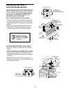
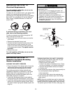
Carriage Bolt
1/4"-20x1/2"
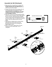
Lens
Wing Nut
Figure 5
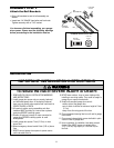
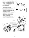
MOUNTING AND WIRING THE SAFETY SENSORS
• Slide a 1/4"-20x1/2" carriage bolt head into the slot
on each sensor. Use wing nuts to fasten sensors
to brackets, with lenses pointing toward each other
across the door. Be sure the lens is not obstructed
by a bracket extension. See Figure 5.
• Finger tighten the wing nuts.
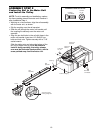
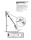
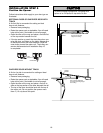
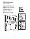
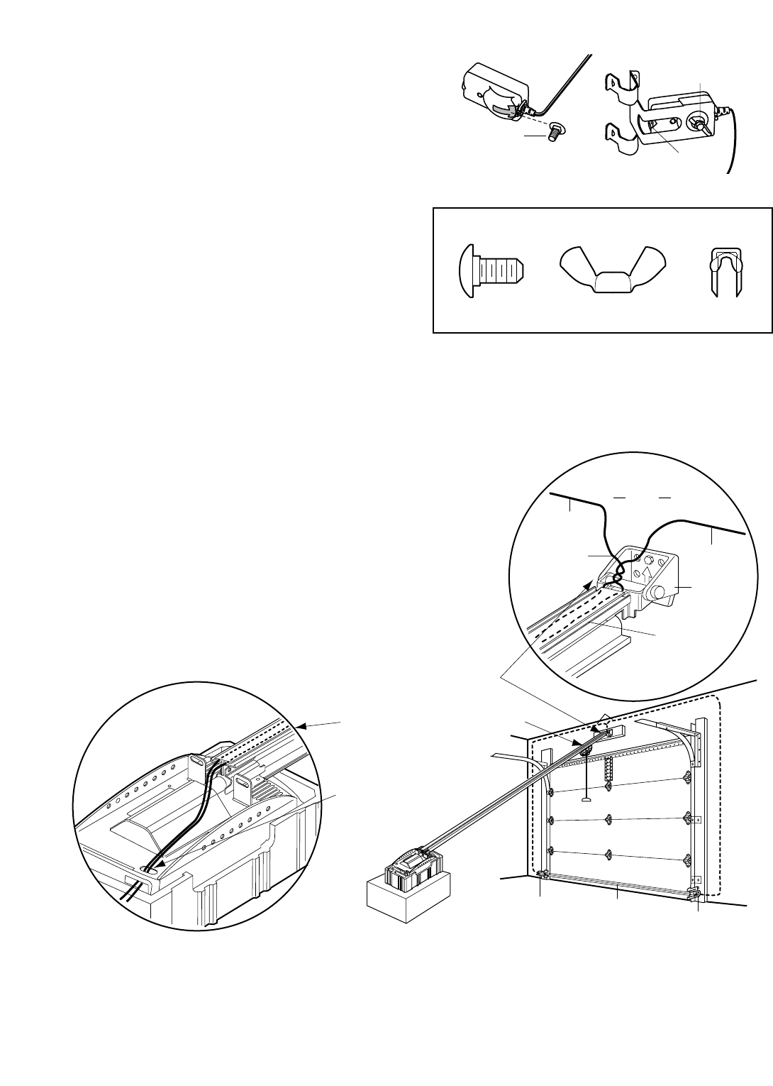
Recommended Wire Routing
1. Using insulated staples, run the wires from both
sensors to the rail at the door header
(see Figure 6).
2. Cross and twist the two wires where they meet
the rail (see Figure 6, Illustration A). Run the wires
inside the channels at the top of the rail, along
each side, to the motor unit. Do not use the lower
(trolley) channels. Use a screwdriver tip to tuck
the wires snugly into the channels.
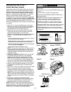
NOTE: If your access door is near the garage
door, you may choose to install the door control at
this time and run the door control wire along the
rail with the sensor wires. Use one rail channel for
the door control wire and the other channel for
both sensor wires. If you choose this option, follow
instructions 1-3 on page 20 now.
3. Pull wires taut across the top of the chassis and
insert into the opening above the terminal block
(see Figure 6, Illustration B). You will complete the
wiring in Installation Step 7.
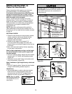
Wing Nut
1/4"-20
Staples
Carriage Bolt
1/4"-20x1/2"
HARDWARE SHOWN ACTUAL SIZE
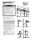
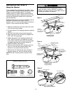
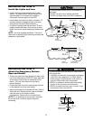
Invisible Light Beam
Protection Area
Sensor
Sensor
Bell Wire
Header
Bracket
Header
Wall
Sensor
Wire
Twist
Wires
Sensor
Wire
Rail
Channel
2. Run wires along channels
to motor unit. Use screwdrive blade
to tuck snugly into channels.
1. Run wires from sensors to end of rail
at the door header. Cross & twist here to
help contain wires in channels on top of rail.
3. Pull wires taut across top of chassis
and insert into opening above
terminal block.
Figure 6
A
B