


14
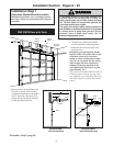
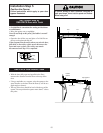
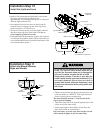
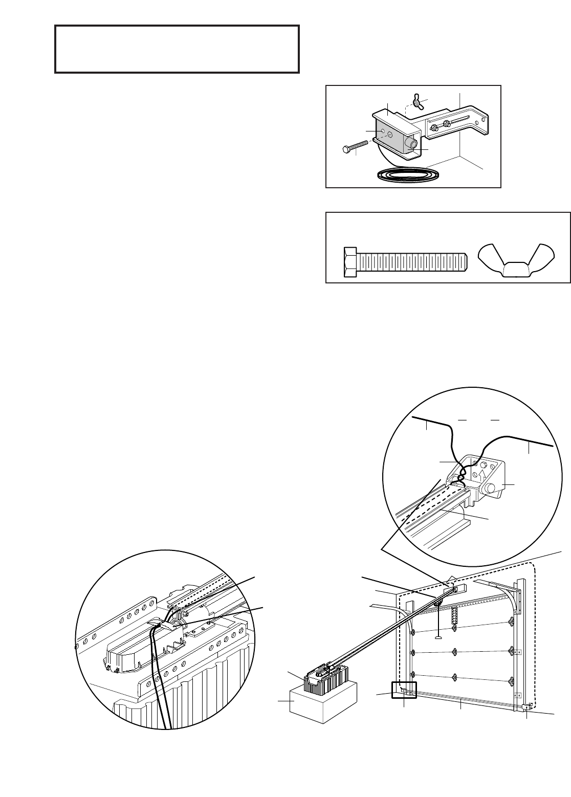
Figure 6
1/4-20 x 1-1/2"
Hex Bolt
"C" Wrap
Sensor
with Wire
Wing
Nut
Indicator
Light
1/4-20 x 1-1/2"
Hex Bolt
Wing Nut
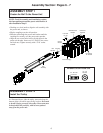
Hardware Shown Actual Size
Installation Step 4 (Continued)
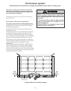
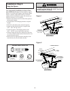
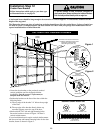
Install the Safety Reversing Sensor
Invisible Light Beam
Protection Area
Sensor
Sensor
Bell Wire
Foam
Packaging
Carton
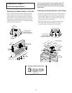
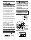
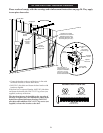
2. Run wires along channels
to power unit and pull taut.
1. Run wires from sensors to end of rail
at the door header. Cross & twist here to
help contain wires in channels on
top
of rail.
3. Thread wires through tabs
on top of Drive Shaft Cover.
4. With screwdriver blade,
tuck wires snugly into channels.
Header
Bracket
Header
Wall
Sensor
Wire
Twist
Wires
Sensor
Wire
Rail
Channel
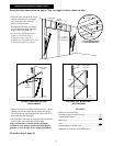
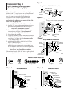
Figure 7
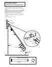
7. Center each sensor unit in a “C”- wrap with lenses
pointing toward each other across the door (see
Figure 6).
8. Secure sensors with the hardware shown. Finger
tighten the wing nut on the receiving eye to allow for
final adjustment. Securely tighten the sending eye
wing nut.
Recommended Wire Routing
1. Using insulated staples, run the wires from both
sensors to the rail at the door header (see Figure 7).
2. Cross and twist the two wires where they meet the rail
(see inset A). Run the wires inside the channels at the
top of the rail, along each side, to the power unit and
pull taut (see inset B). Do not use the lower (trolley)
channels.
NOTE: If your access door is near the garage door,
you may choose to install the door control at this
time and run the door control wire along the rail
with the sensor wires. Use one rail channel for the
wall control wire and the other channel for both
sensor wires. If you choose this option, follow
instructions 1-3 on page 17 now.
3. Thread the wires through the tabs on top of the drive
shaft cover.
4. With your screwdriver tip, tuck the wires snugly into
the rail channels. You will complete the wiring in
Installation Step 7.
A
B