14
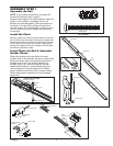
INSTALLATION STEP 2
Install the Header Bracket
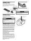
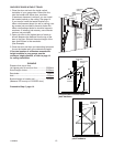
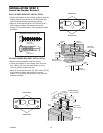
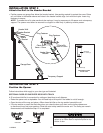
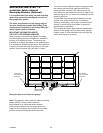
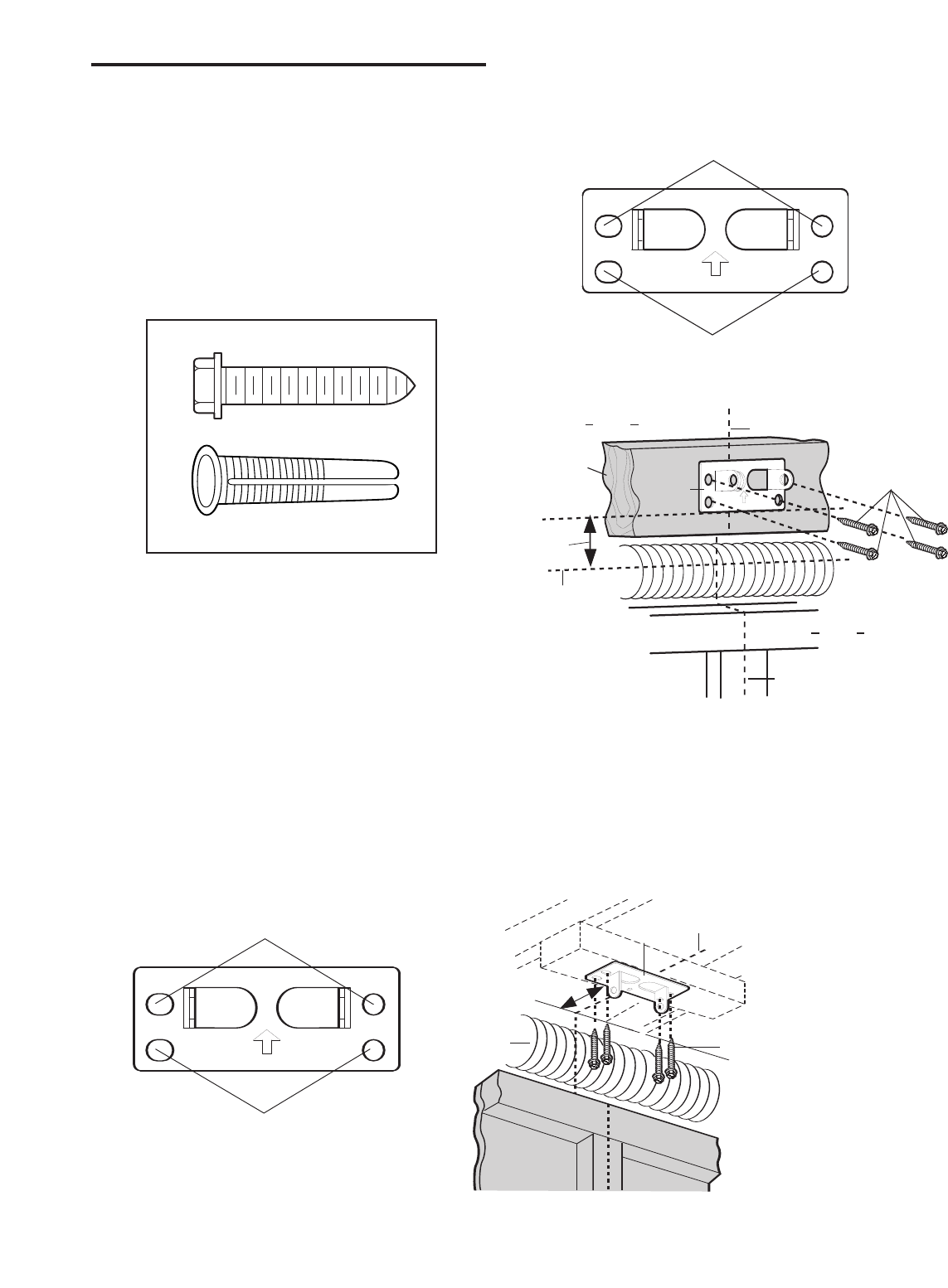
WALL HEADER BRACKET INSTALLATION
• Centre the bracket on the vertical guideline with the
bottom edge of the bracket on the horizontal line
(with the arrow pointing toward the ceiling).
• Mark all of the bracket holes. Drill 4.5mm (3/16")
pilot holes and fasten the bracket with wood
screws. For concrete mount, use concrete anchors
provided.
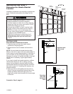
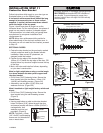
Lag Screw
8mm x 40mm
Anchors
8mm x 40mm
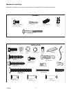
HARDWARE SHOWN ACTUAL SIZE
Lag Screws
8mm x 40mm
Highest Point of
Garage Door Travel
Vertical
Center Line
Header
Wall
Garage
Door
UP
CEILING MOUNT ONL
Y
Wal
l Mounting Holes
Optional
Wall Mounting Holes
The nail hole is for
positioning only.
You
must use lag screws
to mount the header bracket.
UP
CEILING MOUNT ONL
Y
Door Spring
Header
Bracket
25mm
Board
Vertical
Center Line
Bracket Holes
Bracket Holes
50mm
(2")
25mm
Board
Header
Wal
l
Vertical
Centre Line
Lag Screws
8mm x 40mm
Header
Bracket
Highest Point of
Garage Door Travel
Vertical
Centre Line
Garage
Door
UP
CEILING MOUNT ONLY
Ceiling Mounting Holes
The nail hole is for
positioning only.
You must use lag screws
to mount the header bracket.
UP
Lag Screws
8mm x 40mm
Garage Door
Vertical Centreline
Header Wall
– Finished Ceiling –
Header
B
racket
15cm Maximum
Vertical
Centreline
Door
Spring
Bracket Holes
Bracket Holes
150mm
(6")
Door
Spring
Header Wall
Lag Screws
8mm x 40mm
Header
Bracket
Vertical Centreline
– Finished Ceiling –
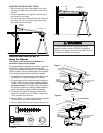
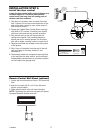
CEILING HEADER BRACKET INSTALLATION
• Extend vertical guideline onto the ceiling.
• Centre the bracket on the vertical mark no more
than 150mm (6") from the wall. Make sure the
arrow is pointing toward the wall.
• Mark all of the bracket holes (5). Drill 4.5mm (3/16")
pilot holes and fasten the bracket with wood
screws. For concrete ceiling mount, use concrete
anchors provided.
114A2845


