


© 2002, The Chamberlain Group, Inc.
114A2633B All Rights ReservedPrinted in China
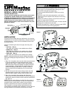
Opener Terminal Screws
2 3
1
BACK PANEL
Quick-Connect™ Terminals
7/16"
Strip wire 7/16"
Door Control
Connections
Red
Black
White
KG
To Replace Insert Bottom Tabs First
Single
Gang Box
24 Volt
Bell Wire
Enlarged
View
Figure 5
Figure 4
FOR WALL BOARD (DRYWALL) MOUNT
Remove the left and right door control buttons by gently twisting
at the top with a small flat blade screwdriver exposing the
horizontal installation holes. Figure 2. Mark and drill wall board.
Drill 7/32" holes and use anchors provided. Fasten with 1-1/4"
self-tapping screws. Do not overtighten. Insert bottom tabs and
snap on door control buttons. Figure 3.
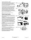
FOR MOUNTING ONTO A SINGLE ELECTRICAL GANG BOX
Remove the center cover or door control button by gently prying
at slot in top of the door control button with a small flat blade
screwdriver exposing two installation holes. Figure 2. For
flexibility, this wall control can be mounted either left or right of
center directly over gang box. Use 6-32X1" machine screws.
Install bottom screw, allowing 1/8" to protrude above wall
surface. Position bottom of door control on screw head and slide
down to secure. Adjust screw for snug fit. Install matching top
machine screw. Do not overtighten. Insert bottom tab and snap
center cover or door control button. Figure 4.
NOTE: Mounting hardware is included for each type of
installation (use all four screws if desired).
USING THE DOOR CONTROL
Press the door control button to open or close the door. Press
again to reverse the door during the closing cycle or to stop the
door while it's opening.
Light feature: Press the Light button to turn the opener light on
or off. Figure 6. It will not control the opener lights when the door
is in motion. If you turn it on and then activate the opener, the
light will remain on for 4-1/2 minutes. Press again to turn it off
sooner. On units that have the adjustable light feature the 4-1/2
minute interval can be changed to 1-1/2, 2-1/2, or 3-1/2 minutes
as follows: Press and hold the Lock button until the light blinks
(about 10 seconds). A single blink indicates that the timer is
reset to 1-1/2 minutes. Repeat the procedure and the light will
blink twice, resetting the timer to 2-1/2 minutes. Repeat again for
a 3-1/2 minute interval, etc., up to a maximum of four blinks and
4-1/2 minutes.
Lock feature: Designed to prevent operation of the door from
hand-held remote controls. However, the door will open and
close from the Door Control, the Outside Keylock and the
Keyless Entry Accessories.
To activate, press and hold the Lock button for 2 seconds.
Figure 6. The door control button light will flash as long as the
Lock feature is on.
To turn off, press and hold the Lock button again for
2 seconds.The door control button light will stop flashing. The
Lock feature will also turn off whenever the “Smart” (learn)
button on the motor unit panel is activated.
NOTE: The lock and light features will work properly on
Security
✚
garage door openers manufactured after 1997.
For further product information refer to your owner’s
manual or go to www.liftmaster.com
Lock
Button
Light
Button
Lock
Button
Light
Button
Figure 6
To Replace Insert Bottom Tabs First
Enlarged
View
Figure 3