


ABC
Select a remote control
push button to operate
each opener
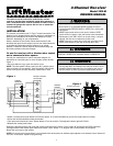
Connect
Antenna
Opener #3
(Blue)
Opener #2
(Yellow)
Opener #1
(Grey)
Slide Switch – N.O. Position
To use the receiver to operate three garage
door openers with a multi-function
remote control:
Garage door opener no. 1 (without transformer)
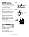
Refer to Figure 3 for wiring connections:
Connect paired grey receiver wires to the opener terminal screws
used for the wall push button.
Also, connect bell wire to receiver terminal 1 and opener terminal
screw 1; and receiver terminal 2 and opener terminal screw 3.
Garage door opener no.1 (with transformer 95)
Refer to Figure 4 for wiring connections:
Connect bell wire to receiver terminal screws 1 and 2, and to
transformer terminals. Also, connect paired grey receiver wires to
opener terminal screws used for wall push button.
Garage door opener no. 2: Connect paired yellow wires from
the receiver to the opener terminal screws used for the wall
button.
Garage door opener no. 3: Connect paired blue wires from the
receiver to the opener terminal screws used for the wall button.
Use a screwdriver to pry open the receiver cover.
Set the slide switch to the N.O. position. If this is not done,
opener #1 may not operate properly.
Re-connect power to the opener(s) and to the transformer,
if used.
• Select a remote push button to operate garage door opener #1.
• Press and hold the selected remote button. Then press and
release the “learn” button labeled “A” on the receiver. The
adjacent indicator light will FLASH.
• Release the remote push button. Opener #1 will now operate
when the selected remote control push button is pressed.
Repeat the procedure with the other two remote push buttons to
program the second opener (“learn” button “B”) and the third
opener (“learn” button “C”). Figure 5.
Return the cover to the receiver.
NOTE: If opener #1 will not run, check to be sure the slide
switch on the receiver is set to the N.O. position.
NOTE: If a remote control push button is not pressed within 30
seconds, the indicator light adjacent to the selected “learn” button
will turn OFF. In that case, repeat the programming.
1
2
3
1
3
Receiver
(Bottom)
Wall
Button
Operator
24 v
Trans
Primary
4
Common
2
Relay
Transformer 95
Paired grey receiver wires
1
2
3
1
2
3
Receiver
(Bottom)
Paired grey receiver wires
Operator
24 v
Trans
Primary
4
Common
Relay
Wall
Button
Figure 3
Figure 4
© 2005, The Chamberlain Group, Inc.
114A3098 All Rights Reserved Printed in Mexico
Figure 5
NOTICE: To comply with FCC and or Industry Canada (IC) rules, adjustment or modifications of this
receiver and/or transmitter are prohibited, except for changing the code setting or replacing the bat-
tery. THEREARE NO OTHERUSER SERVICEABLE PARTS.
Tested to Comply with FCC Standards FOR HOME OR OFFICE USE. Operation is subject to the fol-
lowing two conditions: (1) this device may not cause harmful interference, and (2) this device must
accept any interference received, including interference that may cause undesired operation.
SPECIFICATIONS
Output Rating......................................5 Amps 28VAC or DC Max.
Power.......................................................18 - 30V ~, 30mA, 60Hz
18 - 30V , 30mA
RF Frequency...................................................................315 MHz
If the power is other than shown in specifications, Accessory
Transformer Model 95 is required. Model 86 Coaxial Cable Kit is
also available.
Accessory Transmitters — Series 300.