


17
1
14A2845
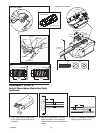
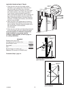
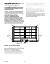
INSTALLATION STEP 6
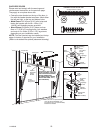
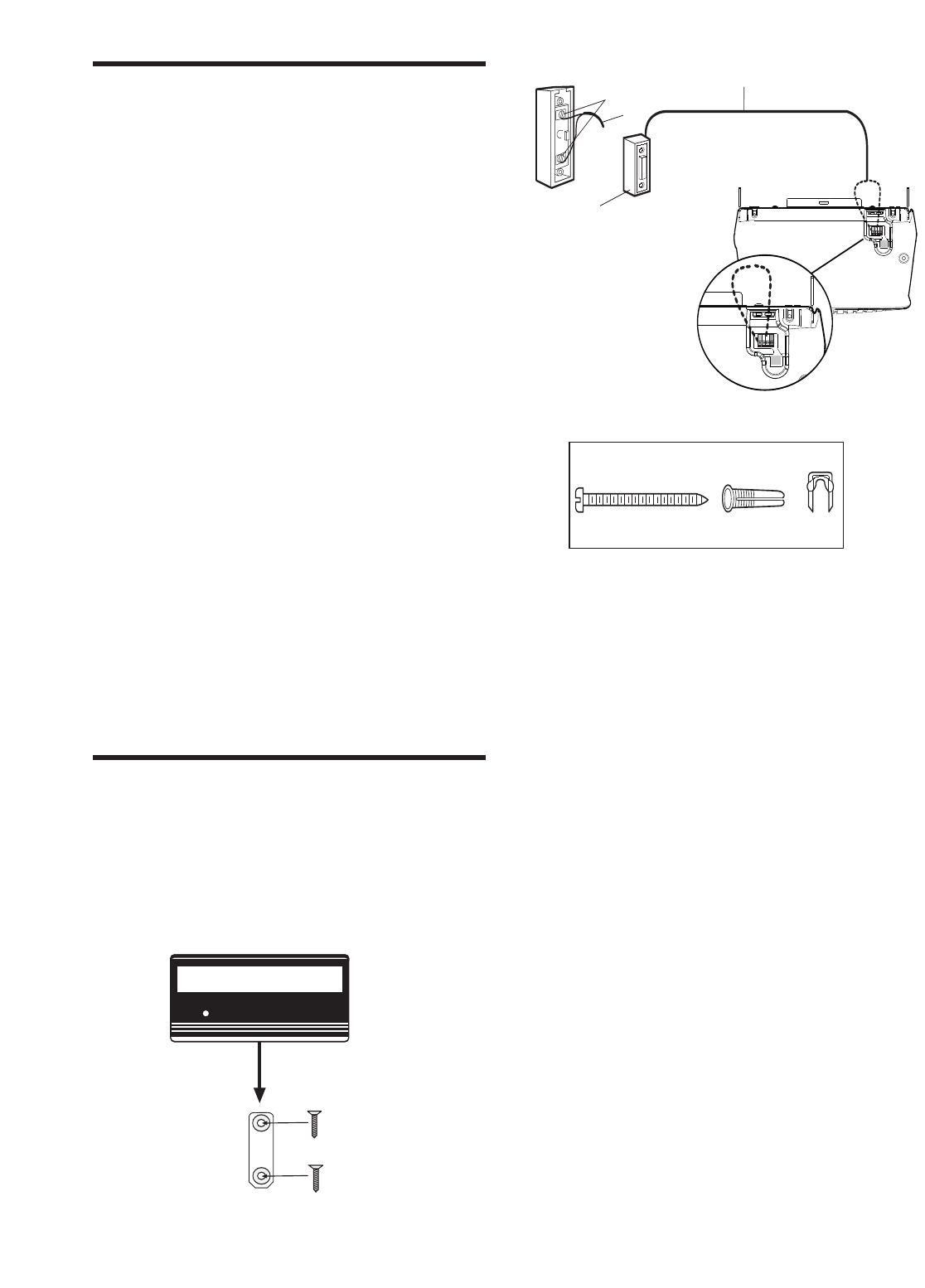
Install the door control
Locate the door control within sight of the door at a
minimum height of 1.5m where small children
cannot reach, and away from all moving parts of
the door and door hardware.
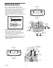
1. Strip 6mm of insulation from one end of the bell
wire. Connect it to the two screw terminals on the
back of the door control by color: white wire to 2
and white/red wire to 1.
2. Fasten the Lighted Door Control Button securely
with 6ABx1-1/2” screws. If installing into drywall,
drill 4mm holes and use the anchors provided.
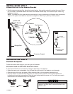
3. Run the bell wire up the wall and across the
ceiling to the opener. Use insulated staples to
secure the wire in several places. Do not pierce
wire with a staple, creating a short or open circuit.
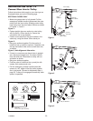
4. Receiver terminals are located on the back panel
of the opener.
5. Strip 11mm of insulation from the end of the bell
wire and insert in wire trap: white to 2 and
white/red to 1.
6. Permanently attach the entrapment warning label
to the wall near the door control, and the manual
release/safety reverse test in a prominent location
on the inside of the garage door.
Bell Wire
The Chamberlain Group, Inc.
Figure 17 - Wall Control
4210E
3/6/92
WHT
-2
RED
-1
Lighted Door
Control Button
Terminal Screws
Lighted Door
Control Button
Bell Wire
Screw 6ABx1-1/2”
Lighted Door Control Button
Drywall Anchors
Insulated
Staples
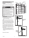
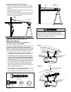
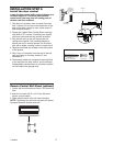
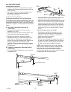
Remote Control Wall Mount (optional)
1. Locate wall mount bracket at least 1.5m above the
floor.
2. Attach to the wall with 2 x ø 3.5 max flat head
screws (not provided).
3. Slide remote control onto wall mount bracket.
NOTE: T
ightening the wall mount screws will reduce
clearance between bracket and wall.
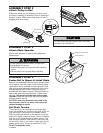
HARDWARE SHOWN ACTUAL SIZE