


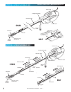
POWER HEAD & RAIL ASSEMBLY
Assembly for CHAIN DRIVE OPENER
NOTE: Handle carefully! Drive chain can slide out of rail.
NOTE: For power head and rail assembly locate
Bag 1 from Box 1.
NOTE: Copy serial number from power head
frame and record it on warranty page.
NOTE: Standing at the powerhead, facing the door,
the bullet MUST be on the RIGHT side of the rail.
NOTE: Standing at the powerhead, facing the door,
the bullet MUST be on the RIGHT side of the rail.
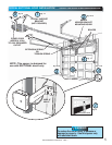
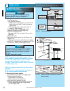
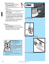
1. Attach rail assembly to power head by aligning
the sprocket onto the motor shaft. Use (3)
bolts, 5/16"-18 x 1/2" (Fig. 1-5).
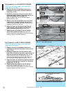
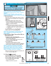
2. Tighten the chain by turning the adjustment
nut clockwise. The chain adjustment nut is
located in the Chain Pulley Bracket (opposite rail
end from the power head) (Fig. 1-6).
3. Tighten chain until chain is approximately 1/8
inch above the base of the rail at midpoint on
the rail (Fig. 1-6). Do NOT over tighten chain.
Set assembled power head and rail aside. Begin with
Section 2 INSTALLATION.
PN# 3642036534, 02/26/2010 REV. 1
11
FIG. 1-6 Chain adjustment.
FIG. 1-5 Rail - Power head assembly.
Chain Pulley Bracket (at wall end of rail)
Chain
T-Rail at center of rail assembly
1/8"
T-Rail
Chain
Tighten nut to move pulley this direction
Use 1/2" socket
on adjustment nut
Use
5/16"-18 x 1/2"
Bolts
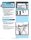
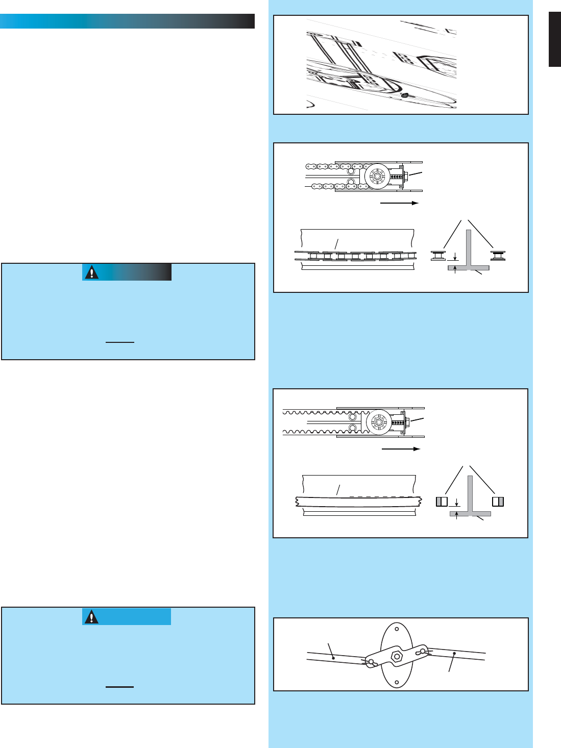
FIG. 1-8 Disable garage door lock.
Remove
Remove
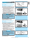
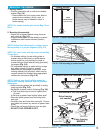
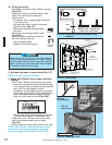
FIG. 1-7 Belt adjustment.
Belt Pulley Bracket (at wall end of rail)
Belt
T-Rail at center of rail assembly
1/8"
T-Rail
Belt
Tighten nut to move pulley this direction
Use 1/2" socket
on adjustment nut
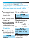
Assembly for BELT DRIVE OPENER
NOTE: For power head and rail assembly locate
Bag 1 from Box 1.
NOTE: Copy serial number from power head
frame and record it on warranty page.
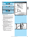
1. Attach rail assembly to power head by aligning
the sprocket onto the motor shaft. Use (3)
bolts, 5/16"-18 x 1/2" (Fig. 1-5).
2. Tighten the belt by turning the adjustment nut
clockwise. The belt adjustment nut is located in
the Belt Pulley Bracket (opposite rail end from the
power head) (Fig. 1-7).
3. Tighten belt until belt is approximately 1/8 inch
above the base of the rail at midpoint on the
rail (Fig. 1-7). Do NOT over tighten belt.
Set assembled power head and rail aside. Begin with
Section 2 INSTALLATION.
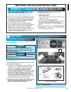
You should have removed all ropes and/or
cables (NOT door lift cables) and disabled
the door lock already. If you have not,
remove all ropes and/or cables and disable
garage door lock NOW
before continuing
with installation (Fig. 1-8).
CAUTION
You should have removed all ropes and/or
cables (NOT door lift cables) and disabled
the door lock already. If you have not,
remove all ropes and/or cables and disable
garage door lock NOW
before continuing
with installation (Fig. 1-8).
CAUTION